ANALYTICAL CALCULATION IN AUTOMOBILE
DESIGN OF AUTOMOBILE ELEMENTS BY ANALYTICAL
- INPUT FROM MECHANISM DESIGN OUTPUT DATA
- FAULT & MAINTENANCE DATA ON WEAR & LIFE CYCLE
- APPLICATION ON PRODUCT/SYSTEM DEVELOPMENT
THREE METHOD OF CALCULATION
- DESIGN KINEMATICS TO THE NEW LOAD DATA
- DESIGN TO CHECK THE LOAD CAPACITY
- CHECKING LIFE CYCLE
list of automotive parts mostly for vehicles using internal combustion engines which are manufactured components of automobiles:
Machine element refers to an elementary component of a machine. These elements consist of three basic types:
- structural components such as frame members, bearings, axles, splines, fasteners, seals, and lubricants,
- mechanisms that control movement in various ways such as gear trains, belt or chain drives, linkages, cam and follower systems, including brakes and clutches, and
- control components such as buttons, switches, indicators, sensors, actuators and computer controllers.[1]
Body components, including windows and trim:
- Bonnet/hood
- Bonnet/hood
- Bumper
- Unexposed bumper
- Exposed Bumper
- Cowl screen
- Decklid
- Fascia rear and support
- Fender (wing or mudguard)
- Front clip
- Front fascia and header panel
- Grille (also called grill)
- Pillar and hard trim
- Quarter panel
- Radiator core support
- Rocker
- Roof rack
- Spoiler
- Front spoiler (air dam)
- Rear spoiler (wing)
- Rims
- Trim package
- Trunk/boot/hatch
- Trunk/boot latch
- Valance
- Welded assembly
- Front Right Outer door handle
- Front Left Side Outer door handle
- Rear Right Side Outer door handle
- Rear Left Side Outer door handle
- Front Right Side Inner door handle
- Front Left Side Inner door handle
- Rear Right Side Inner door handle
- Rear Left Side Inner door handle
- Back Door Outer Door Handles
- Front Right Side Window motor
- Front Left Side Window motor
- Rear Right Side Window motor
- Rear Left Side Window motor
- Door control module
- Door seal
- Door water-shield
- Hinge
- Door latch
- Door lock and power door locks
- Central-locking
- Fuel tank (or fuel filler) door
Mechanical elements
- Belt, Chain, Cable drives
- Clutch
- Brake
- Gear train
- Cam and follower systems
- Linkage
- Simple machine







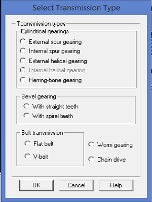
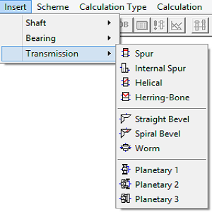
TRANSMISSION APM - calculation module and design of mechanical gear rotation
OUTPUT
- CALCULATION DATA
- EXPORT DXF 2D FILE
- APM GRAPH 2D FILE
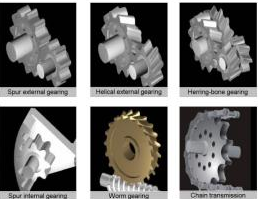
TYPE
- DESIGN
- LONGEVITY CHECKING
- TORQUE CHECKING

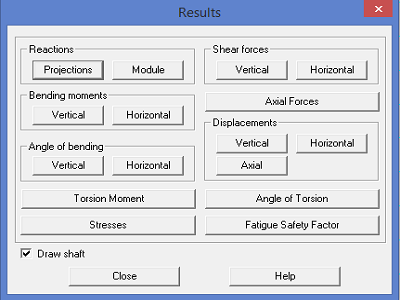
SHAFT APM - calculation module and design of shafts and axles. General and Dynamic calculation
TYPE
- DESIGN
- LONGEVITY CHECKING
- TORQUE CHECKING

OUTPUT
- CALCULATION DATA
- EXPORT DXF 2D FILE
- APM GRAPH 2D FILE
Structural elements
- SHAFT
- ROTATING SPINDLE
- GEAR SPINDLE
- TRANSMISSION SHAFT
- PROPELLER SHAFT
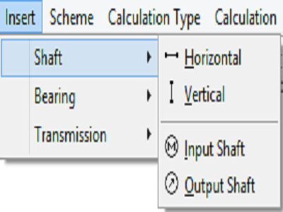
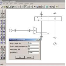
DRIVE APM - aided design module drive rotational movement
of any structure. CALCULATION OF BEARING/SHAFT/GEAR TRAIN
TYPE
- DESIGN
- LONGEVITY CHECKING
- TORQUE CHECKING
OUTPUT
- CALCULATION DATA
- EXPORT DXF 2D FILE
- APM GRAPH 2D FILE



JOINT APM - calculation module and design of machine elements connections
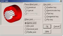
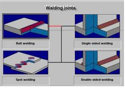
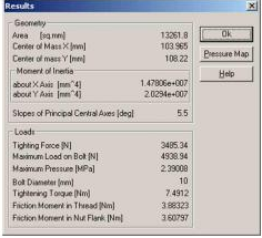
APM Joint - Elements and units of the machines, mechanisms and constructions are joined together by means of the special elements or without them, producing new constructions and units as the totality of the smaller ones. There are many ways of element joining and many methods of the calculation and the design of such joints. Different types of machine element joints are used in the mechanical engineering— threaded,welded, riveted, keyed, splined, etc. You can design and calculate all these objects with the APM Joint. APM Joint is a software for the machine element joints calculation and design. It allows to perform a complex calculation and analysis of the most widely used types of joints. The use of this software reduces design time, increases design reliability and efficiency, helps to select the optimal decision.
APM Joint can calculate the following joints
Threaded opened and closed joints , with any element arrangement, arbitrary configuration of surfaces to be joined and arbitrary loading In addition bolts, screws and studs can be calculated as fastening elements under arbitrary external load
Welded joints with the arbitrary arrangement of seams under the arbitrary external load, including butt joints - tee joint - lap joints joints produced by the spot weld. riveted joints of the arbitrary arrangement under the arbitrary plane loading
Joints of the rotating elements such as - interference fits of the cylinder and cone shape - splined and keyed joints - radial and axial pins (gluts)
joints with cone rings - terminal joints - profile joints
APM Joint calculations
The criteria for the threaded joints calculation is the absence of the shearing and the absence of the opening of the conjugate surfaces, as well as the static strength and the fatigue strength; welded seams are calculated for the static and the fatigue strength; riveted joints are checked for the strength under the constant load.
APM Joint calculations
Either absence of the shearing and non-opening or the static and the fatigue strength of the joint elements or both the former and the latter can be used(depending on the type of the joint) as a criteria for the joints of therotating elements.
It is possible to create the designed models bothin APM Joint editor and in other graphics systems, which support export to*.dxf.
Besidescalculation facilities APM Joint provides user with the functionally completeintegrated environment that includes:
specializedgraphical editor
versatile toolsfor calculation results presentation
editable built-in data base - dxf files import functionality
Completeintegrated environment
APM Joint allows to perform all types of the design and checking calculations. The formerincludes determination of the joint dimensions for the given loading, the latter— the safety factors calculation.
OUTPUT
- CALCULATION DATA
- EXPORT DXF 2D FILE
- APM GRAPH 2D FILE
TYPE
- DESIGN
- LONGEVITY CHECKING
- TORQUE CHECKING
SCEW APM - calculation module imperfect helical gears (sliding, ball-screw and planetary)
Apm Screw
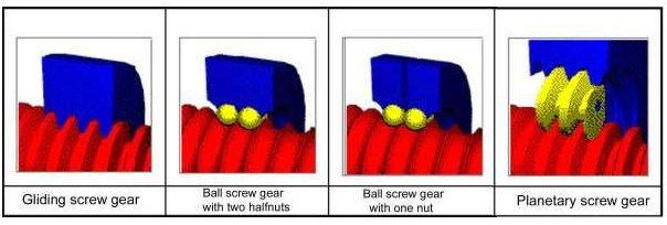
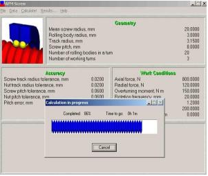
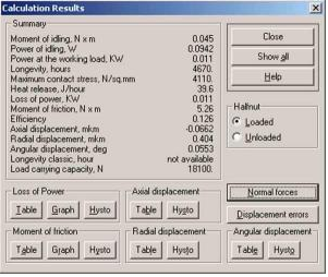
APM Screw is comprehensive software for calculation of screw gears. It allows you to perform a complex analysis of the screw gears, compute its main performances, and select the optimum parameters of gear elements.
APM Screw - Screw gears are used for transformation of rotational movement of the screw to the transactional movement of the nut. They are widely applied in the machine tool industry, aircraft industry, roboto technics and many other areas of the modern mechanical engineering. Mean while, the existing methods of screw gear calculation collide with number of the serious problems.
APM Screw is a comprehensive software for calculation of screw gears. It allows you to performa complex analysis of the screw gears, compute its main performances, and select the optimum parameters of gear elements. The most widely used types of the screw gear
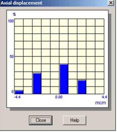
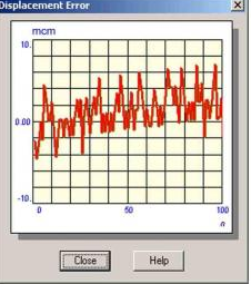
In the APM Screw you can calculate the most widely used types of screw gears. For the ball screw gears two sub types can be calculated — with one nut and with two half nuts (the latter allows the preload use). The theory of the non-ideal contact—the basis of the APM Screw. The main advantage of the APM Screw is that it allows considering the influence of manufacturing errors on the screw gear performances. It becomes possible due to the new theory of non-ideal contact, developed in the Research and Software Development Center APM Ltd. This theory is applicable to the wide range of machine elements, such as bearings, screw gears, plain joints, rolling contact guides,etc. It allows you to get reliable values of the contact displacements,stiffness, stresses and all parameters that are depended on the formers, such as longevity, moment of friction, loss of power, etc.
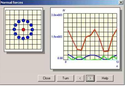
For the moment of friction and loss of power a list of 100 values is calculated, so you can determine the features of the distribution of these parameters. The results can be presented either as tables, as histograms or as graphs. The heat release is an integral parameter characterizing the amount of the heat released in the gear due to the friction during a time period of one hour. An arbitrary loading conditions including the preload
Calculations in the APM Screw can be made for any combination of axial and radial forces,over turning the moment and the preload allowed for a screw gear of the given type. External loads by longevity calculation can be considered to be variable in time. There is a special graph editor for that purpose.
TYPE
- DESIGN
- LONGEVITY CHECKING
- TORQUE CHECKING

OUTPUT
- CALCULATION DATA
- EXPORT DXF 2D FILE
- APM GRAPH 2D FILE
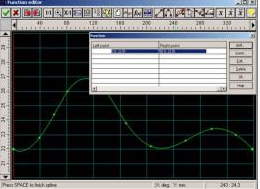
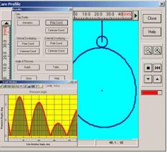
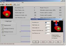

CAM APM - calculation module and design cam mechanisms
APM Cam is intended for cam mechanism calculation and design.
APM Cam
Cam mechanism isthe elementary mechanism that is used to transform rotational movement to translation or hobbing motion of pusher. The pusher motion law of cam mechanismis defined by cam geometry and pusher type. Cams are frequently used as controlunit providing required motion low.
APM Cam is intended for cam mechanism calculation and design.
Main Features Cam design
Function law defined by displacement, velocity, acceleration;
Working drawing generation.
The following types of cams mechanisms can be designed
- cam mechanism with roller arm - cam mechanism with flat arm;
- cam mechanism with roller rocker - cam mechanism with flat rocker.
Initial data
Motion law can be defined as - displacement graph - velocity graph
graph of acceleration by rotation angle of cam.
To design cam mechanism you need to specify cam type, motion law, some geometry parameters of cam and material properties.
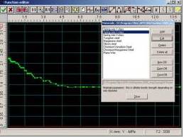
The universal function editor is used to enter motion law function that can consist of several segments represented as linear segments, splines or any their combination. The function law can be defined as analytic function as well.
Calculation criteria - Cam profile is calculated based on pusher motion law, diameter — based on pressure angle limitation, and pusher width and radius — based on maximum contact stress.
Calculation results - APM Cam let cancalculate the following characteristics of cam - cam profile both in Cartesian and polar coordinates - angle of pressure - coordinates of the internal and external envelopings of central profile (for cam with rollers) - animation of cam behavior - create working drawing = Working drawing generation
With APM Cam you can generate the working drawings of the cam profile in the APM Graph file format. Further it can be exported in DXF file by user request. APM Cam allows you to change the geometrical parameters of the cam, motion law, and analyze the graph of speed and acceleration. On the basis of this information you can draw a conclusion about correctness of this cam decision.
OUTPUT
- CALCULATION DATA
- EXPORT DXF 2D FILE
- APM GRAPH 2D FILE
TYPE
- DESIGN
- LONGEVITY CHECKING
- TORQUE CHECKING
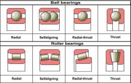
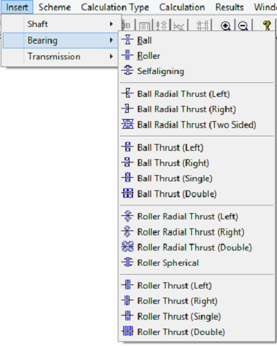
BEAR APM - a module for calculating and designing rolling bearing assemblies with regard to their accuracy class
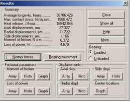
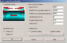
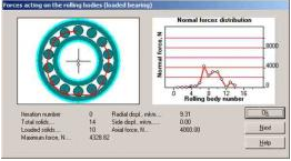
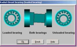
APM Bear Rolling are the main type of supporting units for rotating parts of machines,instruments, apparatuses, various mechanical devices and systems. APM Bearperforms a complex analysis of rolling contact bearings. When using it you can calculate main bearing characteristics and select the optimal constructions ofthe bearing units. Highly of the non-ideal bearings calculation.
APM Bear is a state of the art software for thecalculation of non-ideal bearing parameters.
A bearing is considered non-ideal if its manufacturing errors cannot be ignored in the context of the problem to be solved. Many important problems of the contact stiffness and strength require a bearing to be considered non-ideal.The Centre APM has developed the universal method for solving contact problems.Reliability and effectiveness of this method are proved by series of the experimental researches. The most important bearings parameters are calculated. Our software helps to design rolling-contact bearing optimum by stiffness and other criteria.
Result representation
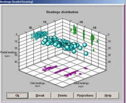
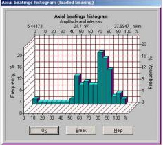
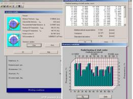
Tables Of Static Characteristics - Histograms Graphs Of Parameters Depending On Rotation Angle 3D Field Of Bearing Center Position
Animation Of Bearing Movement All This Forms Of Presentation Give Authentic View About Bearing’s Movement. You Can Turn The Frictionless Bearing In Order To Watch Changing Applied Bearing Loads.

OUTPUT
- CALCULATION DATA
- EXPORT DXF 2D FILE
- APM GRAPH 2D FILE
TYPE
- DESIGN
- LONGEVITY CHECKING
- TORQUE CHECKING
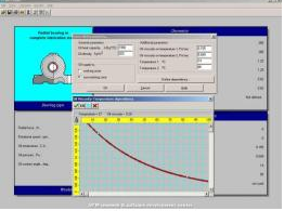

PLAIN APM - calculation module and design of plain bearings
APM Plain
APM Plain Plain bearing is an important type of the rotation supports that is frequently used in complex environments under high vibration and shocks,very low and very high rotational speed, high demands on the shaft stability and accuracy, for the units working in the water and in the aggressive environments, in the absence or lack of the lubrication, etc.
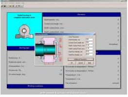
The reliability of the bearings determines the reliability of the equipment they are installed in. APM Plain performs a complex analysis of the plain bearings. When using the system you can determine the basic parameters of the bearing and select the optimum construction of the bearing unit.
Plain bearingtypes - Radial Bearings - In Fluid Lubrication Mode
Radial Bearings - In Semifluid Lubrication Mode
Thrust Bearings - In Fluid Lubrication Mode
APM Plain One Can Calculate Radial And Axial Clearance Distribution -Optimum ClearanceValue Lubrication SystemParameters (Oil Film Thickness - Maximum And Average Oil Temperature - Oil Consumption) -True Friction Coefficient And Loss Of Power - Optimum Dimensions Of The Bearing Elements. Calculation criteria and methods - Calculation criterion for radial bearings that work in the fluid lubrication mode is the condition of minimum allowed clearance between bearing contact surfaces
Calculation criterion for radial bearings that work in the semifluid lubrication mode is requirement for bearing working temperature to be less than the maximum allowed one for given oil.
Calculation of radial bearings that work in the fluid lubrication mode is performed by Reynold's equation solution. So the fluid flow is considered to be laminar.
Calculation method of radial bearings that work in the semifluid lubrication mode is based on analysis of heat release by friction and solution heat transfer equations.
OUTPUT
- CALCULATION DATA
- EXPORT DXF 2D FILE
- APM GRAPH 2D FILE
TYPE
- DESIGN
- LONGEVITY CHECKING
- TORQUE CHECKING
TYPE
- DESIGN
- LONGEVITY CHECKING
- TORQUE CHECKING
OUTPUT
- CALCULATION DATA
- EXPORT DXF 2D FILE
- APM GRAPH 2D FILE

SPRING APM - calculation module and design of elastic elements of cars
APM Spring
Machine elementsthat have high compliance and minimum dimensions are called elastic elements.They are used as loading devices, as shock absorbers, dissipating energy of theshocks, as devices for the energy accumulation, etc. Elastic elements are ofsignificant importance for the modern machines by increasing longevity of thelatter due to the vibration damping and to the resonance frequenciesregulation.
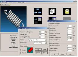
Features - Various springs design - Static and fatigue calculation - Working drawings generation - Adding new materials and correction of the existent.
APM Spring is a system for the calculation and design of elastic machine elements. It allows to perform design and checking calculations and to generate working drawings of elastic elements. Design calculations allow to determine dimensions of elastic elements based on the given external loading and on deformations. Checking calculations allow obtaining strength safety factors depending on the elastic element dimensions.
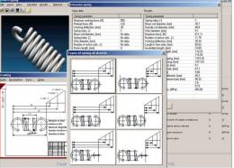
Types of elasticelements
Cylindrical tensional springs with round and rectangular cross-section - Cylindrical compression springs with round and rectangular cross-section
Cylindrical torsion springs with round and rectangular cross-section - Disk compression springs - Flat rectangular springs - Torsion bars.
Types of elastic elements
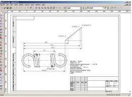
Calculations can be made for both constant and variable loading. The calculations are based on the determination of the static strength under constant loading and of the fatigue strength under variable loading. It is possible to perform the finite element analysis of a spring in APM Structure3D module. Working drawings generation - APM Spring allows generating complete working drawing of the springs and torsion bars. Drawing is created inAPM Graph file format and can be exported in DXF format using APM Graph functionality.

Graph APM - flat parametric drawing and editing tool with a calculation of dimensional chains
APM GRAPH
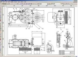
APM Graph is intended for performance of the graphical part of the computer-aided preparation of design documents. It is an integral part of the APM WinMachine system, but it can be used independently. APM Graph represents a 2D graphics editor, which can be successfully used to design a graphical part of design documents in different engineering field, science, architecture and construction.
A drawing is the base of the designed machine elements. As the majority of the system modules allow to get a drawing of the designed part at the output,then for the final drawing design in the form of the document it is necessary to finish it off and to get a firm paper copy. The APM Graph graphic editor,that constitutes a part of the APM WinMachine - performs these and others functions.
APM Graph as an element of the computer-aided design system
APM Graph is intended for performance of the graphical part of the computer-aided preparation of design documents. It is an integral part of the APM WinMachine system, but it can be used independently. APM Graph represents a 2D graphics editor, which can be successfully used to design a graphical part of design documents in different engineering field, science, architecture and construction.
It can be efficiently used to prepare initial data during operation of APM WinMachine separate modules. For this purpose each application program is able to import graphical information.
BASE APM - Module to create and edit database
APM DATA
APM Mechanical Data Main features numerical data graphical data intergationwith APM WinMachine modules quick customization The database APM Mechanical Data can be logically divided into two parts – the informational and the graphical. The informational database contains numerical data characterizing qualities of the materials, tolerances and interference, as well as kinematic, energy,geometry and the other parameters needed for the operation of the other APM...

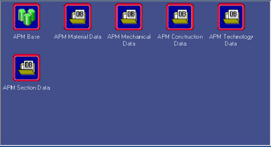
APM Mechanical Data Main features -numerical data - graphical data - integration with WinMachine modules - quick customization
The database APM Mechanical Data can be logically divided into two parts –the informational and the graphical. The informational database contains numerical data characterizing qualities of the materials, tolerances and interference, as well as kinematic, energy, geometry and the other parameters needed for the operation of the other APM WinMachine modules and for the finding of the information required for the design decision making.


