Strength calculation of a five-story brick dormitory building on the ground
and a special combination of loads
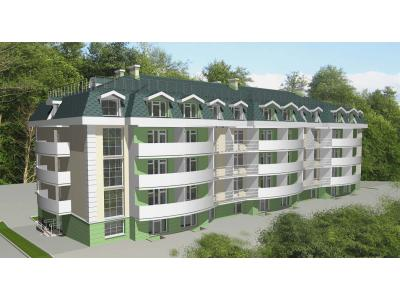
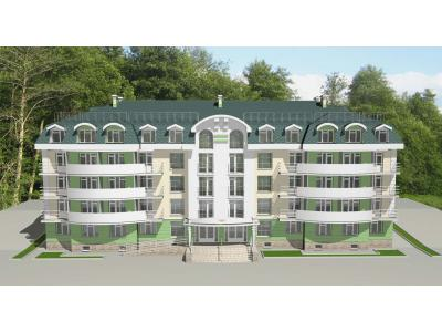
On the basis of the agreement concluded between our organization and LLC "ChernomorStroyProekt" the summer of 2008 was carried out strength calculation of a five-story brick dormitory building on the ground and a special combination of loads. Detailed documentation (floor plans, pile field plan, etc.) provided by the customer. Construction of the building will take place at n. Novomikhailovsky Tuapse district.
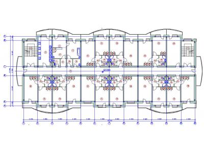
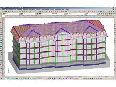
After careful study of the drawings presented consistently been created: the "zero" floor - tehpodpole, first floor, typical floors from the 2nd to the 4th and last floor - the 5th and the roof frame with the coating.
Description of the building structure:
Structurally, the building circuit is a brick structure, with longitudinal and transverse supporting walls. Foundation - monolithic w / w grillage of bored piles. Tehpodpolya walls - monolithic w / w 500, 400, 300 mm of concrete B10 class. The walls of the building are performed masonry of clay fired brick. Overlaps floors - monolithic w / w 160 mm thick concrete class B20. The partitions inside a building brick 65 and a thickness of 120 mm. Building a gable roof with rafters of boards (pine), laid on a steel frame
Description of the complex loads:
loads Setting carried out in accordance with SNIP 2.01.07-85 * "Loads and effects" and SNKK 20-303-2002 "Loads and effects of wind and snow load (TSN 20-302-2002 Krasnodar Region)" .
Automatically with the necessary reliability on the load factor is taken into account its own weight of the structure. There is also a constant stress have been ranked and given the weight of partition walls of bathrooms and loads of earth pressure on the wall tehpodpolya. How short were applied regulatory burden on attics, balconies, living rooms slab, offices, utility rooms (kitchen, showers, toilets), corridors, lobbies, stairs with appropriate safety factors of load.
In accordance with the regulations, we determine that the construction site is located in the I-th Snow district and III-eat windshield area. This information will help to make the design snow and wind effects. Adopted by the seismic design of the building: 8 points.
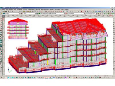
The combination of loads and load combinations calculation: Calculation of stresses acting in the roof structure elements (metal construction and wood frame system), and the load on the foundation supporting action carried out by linear combination of loads. Load factors in combination act reliability values for load factors and combinations of factors. For the main load combinations most unfavorable combination is, at all loads which act simultaneously. When forming the combination into account combinations of coefficients according to p. 1.12 [snip 2.01.07-85 * Loads and effects] for the primary coupling and n. 2.1 [snip II-7-81 construction in seismic regions] for a particular combination.
The combination of loadings for the most unfavorable combination of the main
uploading | type of loading | Coefficients. Reliability | Coefficients. combinations | The product of |
standing | standing | 1.1 | 1 | 1.1 |
regulatory | short | 1.3 | 0.9 | 1.17 |
Snow | short | 1 | 0.9 | 0.9 |
Wind | short | 1.4 | 0.9 | 1.26 |
Table - Combination loadings for the most unfavorable combination of special
uploading | type | Coefficients. Reliability load, | Coefficients. soche-Tania | PRODUCTION denie | The final factor. (The sum of the coefficients. For one loading) |
standing | standing | 1.1 | 0.9 | 0.99 | 1,155 |
Constant (Vertical. Seismo). | special 15% | 1.1 | 0.15 | 0,165 | |
regulatory | short-time | 1.3 | 0.5 | 0.65 | 0.845 |
Regulatory (Vertical. Seismo). | special 15% | 1.3 | 0.15 | 0,195 | |
Snow | short-time | 1 | 0.5 | 0.5 | 0.65 |
Snow (Vertical. Seismo). | special 15% | 1 | 0.15 | 0.15 | |
seismic survey (Horiz.) | a special 100% | 1 | 1 | 1 | 1 |
The main parameters of the materials used in the construction are shown in the table below.
Name | Young's modulus [N / mm ^ 2] | Coefficients. Poisson | Density [kg / kb.mm] |
Pine | 9000 | 0.01 | 5e-007 |
Steel | 200000 | 0.30 | 7.8e-006 |
masonry | 2080 | 0.25 | 1.8e-006 |
Heavy concrete B15 | 24000 | 0.20 | 2.503e-006 |
Heavy concrete B20 | 27500 | 0.20 | 2.503e-006 |
Heavy concrete B25 | 30000 | 0.20 | 2.503e-006 |
The results of calculations.
Conducting statistical analysis showed that the maximum stresses caused by the combination of loads with seismic loads. This can be judged by analysis of reactions in the supports. The calculation results are given for a particular combination of loads as the most dangerous.
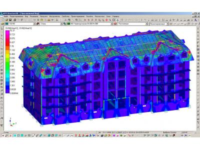
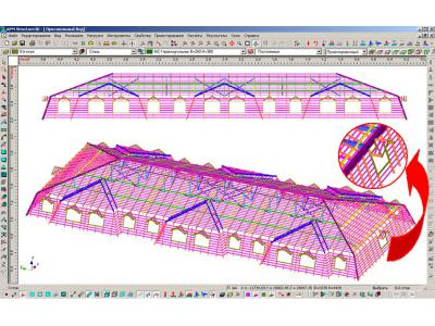
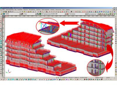
Rafter system and metal structure are a unitary structure and the load together perceive that allows uniform distribution of forces between the structural elements. The maximum stress in the metal does not exceed 80 MPa. Calculated resistance Stali3kp (S235) when the operating conditions coefficient y = 0,9 is: yR = 0,9 * 235 = 211 MPa. Thus, the strength condition Rmax <R (80 <211) is satisfied. the safety factor is: n = r and / Rmax = 211/80 = 2,6. Map equivalent stress for roof system (Fig. 30) Rmax the maximum voltage does not exceed 5 MPa. The calculated resistance of pine wood according to table 3 [SRT 36554501-002-2006 wood and glued solid wood construction. Methods of designing and calculating] in bending, compression and crumpling along fibers for wood varieties II: = r and Rc = Rsm = 13 MPa. Thus, the strength condition Rmax <R (5 <13) holds. the safety factor is: n = r and / Rmax = 13/5 = 2,6.
To account for the seismic effects were calculated own design frequency.
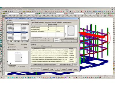
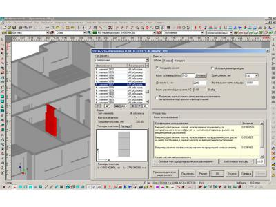
Next, we calculated and checked reinforcement w / w plates, columns, raft foundation, stone walls and floors. Examples of the calculated information output shown below.
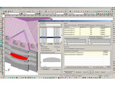
Also, as a visual display of the results can be shown the card utilization rates of reinforcement in plates overlap.
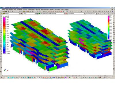
seen from the map - utilization rates of reinforcement is less than unity. It can be concluded that the applied reinforcement provides strength for the first and second groups of limiting states.
According to the results of calculation of masonry structures shows that, for all components utilization rates less than one. Consequently, the strength condition is satisfied brick walls. Calculated reinforcement stone structural elements is not required. It is necessary to carry out structural reinforcement provided by item. 7.6.13 [SP 31-114-2004 Rules design of residential and public buildings for construction in seismic areas].
Finally, in accordance with SP 50-102-2003 "Design and installation of pile foundation" piles was calculated, the results of which indicated that provides load-bearing capacity of the pile-stand on the ground and on the material, as well as the calculation of pile runs on joint action vertical and horizontal forces and torque and a transverse force action.


