Examination of fracture bridge across the river Gums
Organization of the Russian Environmental Fund "TEHEKO" was created in order to implement programs of environmental, financial and economic, industrial and technological security of enterprises and organizations.
By order of the organization "TEHEKO" was performed strength analysis of the pillars of the bridge across the Desna River.
Construction of models and the full range of calculations were carried out using 64-bit version of the design module APM Structure3D.
Concept of the problem:
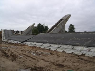
In the process of reconstruction of the bridge at a certain stage of dismantling the old span beams, was its destruction. The main objective was to review and analyze the behavior of how the individual supports and the whole of the bridge as a whole, in various stages of disassembly of superstructures on the right side of the bridge, in accordance with the implementation schedule.
Calculation of bridge construction:
Within the framework of a given problem, we consider the calculation of the fourth support, as well as the calculation of the bridge, beginning with the fourth bearing and finishing ninth.
Modeling support №4
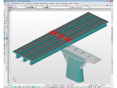
When building the model there are two types of finite element (FE) modeling for finite element solid concrete core and FE modeling for reinforcement.
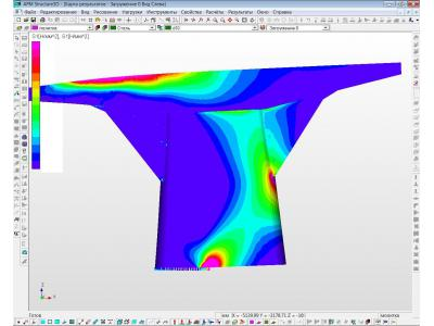
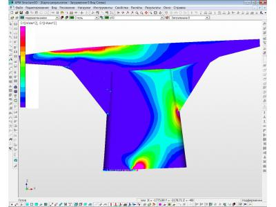
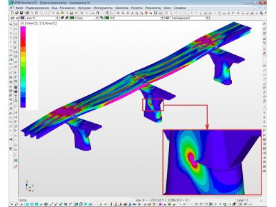
Consistency operation is ensured by a complete coincidence of nodes and rods solids. To obtain a reliable picture of the best way to approach the distribution map of the principal stresses S1. Positive values of the principal stresses will characterize the stretching zone.
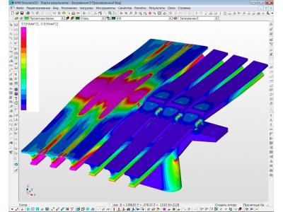
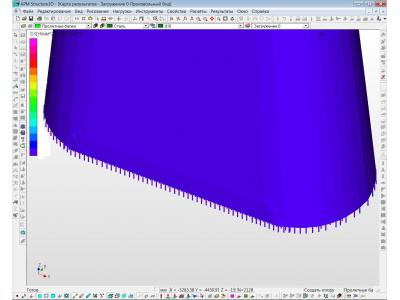
As seen from the results in the card edge docking location and support body has a splash tensile stresses. However, this spike is, only the result of error modeling docking space, characterized by the transition from 8 to 4 ex-nodal finite element. The actual level of effective stresses must be evaluated at 2-4 and a layer of finite elements will be slightly lower value by about 10-15%.
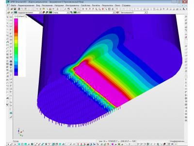
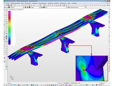
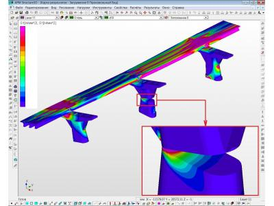
The figures below show the consistent interface disclosure in support of manufacturing defect area due to significant tensile stresses.
Card distribution of principal stresses on the support №4 after dismantling
imulation supports №4-9:
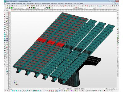
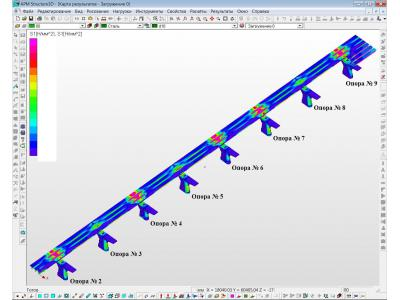
Now consider a model of three pillars of the bridge as a unified design scheme in the last stage of dismantling the old span beams right side of the bridge.
To simulate the compatibility with adjacent elements bridge spans the right end beams (length which is exactly half the real beam length) fixed by preventing movement along the beam axis, thereby providing accounting and the presence of adjacent support beams span
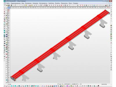
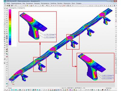
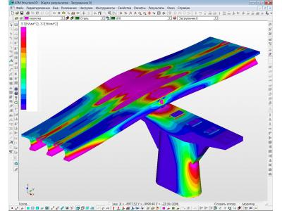
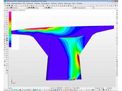
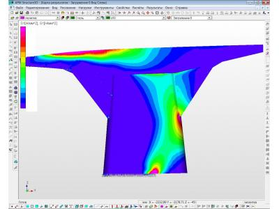
Modification of the bridge at the last stage of dismantling the old span beams right side of the bridge are shown in the figures below.
Card distribution of principal stresses on the supports №4-6 after the dismantling of the old span beams right side of the bridge.
Conclusions:
The work was performed in its entirety. The results obtained are reliable and confirmed by the real picture of the destruction of the bridge.
The calculations are performed Shanin Dmitry |


