KOMPAS ADD ON FEATURES
The following objects can be used as templates for designing with the Steel Structures 3D add-on:
Straight sketch segments - Poly line segments - Straight edges of solids. Profiles can be selected from the template folder. The structure’s position can be set or modified. Displacement directions and part turns are displayed when changing the orientation of the structure. Various ways of orientating structures spatially and the processing of parts are accessible
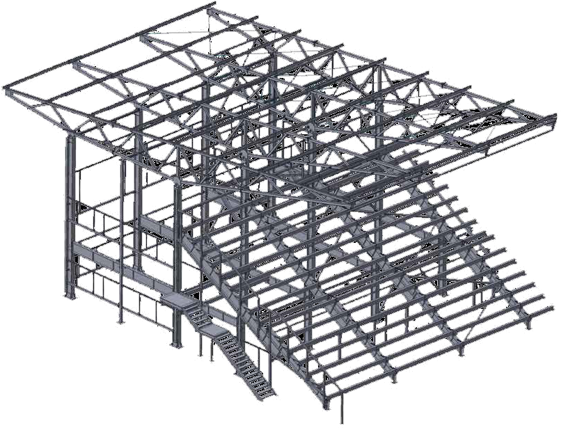
STEEL STRUCTURE 3D
Lengths of profiles can be modified, on the basis of steel structure parts created from the by the Steel Structures 3D add-on. Easy editing allows changing parameters of existing objects, such as trimming and extending.
This add-on also generates reports on selected objects. The report can be previewed and objects can be grouped by their properties. The report can be saved as a KOMPAS-3D document, or as a spreadsheet table that can be read by Open Office. and Microsoft Excel.
The BOM Wizard generates a comprehensive range of customization bills of material. These tables of parts can be associated with 3D assemblies, as well as and 2D assembly drawings of one or more sheets. Works with KOMPAS-3D.
Data can be linked automatically between drawing and model elements and the BOM. The item numbers of assembly parts are transferred from BOMs to drawings. Zone numbers containing images of related parts are transferred from assembly drawings to BOMs. Names, designations, and other data are transferred from parts and assemblies to BOMs.
When assembly drawings contain standard part images from application libraries, then the information about the images are transferred to the BOM.
BOM Wizard
A variety of parameters and settings allows you to create custom forms, in addition to forms that meet the Euro-Asian GOST standards. Examples include BOM lists, referenced documents lists, communication charts, and change orders. The BOM Wizard supports the semi-automatic filling of items and sub-items, and standard sorting within item groups. Sorting rules can be modified by you. BOM Wizard tools are excellent for working with different kinds of specifications, catalogs, and lists. You can numbers lines, sort the content, and associate them with documents and other graphical objects.
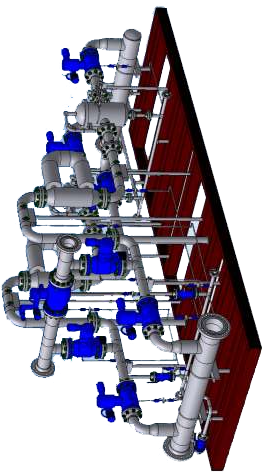
Pipelines3D
The Pipelines 3D add-on automates piping design. It is also suitable for use with the design of pipes in machinery and utility networks. You can create piping layouts from existing layouts, from existing document paths or by their elements, or as arbitrary layouts. Works with:KOMPAS-3D. This add-on offers the following features: Creates piping layouts, perform a variety of editing operations on them. Manually arranges the pipeline’s elements. Arranges elements and specifies specific types of couplings for each element. Allows different insets for pipes. Cuts selected pipe couplings. Rearranges bearing faces-Edits diameters and wall thicknesses of pipes. Pipelines can be created automatically,semi-automatically, or manually. In automatic mode, layouts are defined by routes, and each route can include several paths.
This mode sets tees, outlets,and cutting of selected pipe couplings based on the paths included in the routes.
In semiautomatic mode, pipelines are created by selected segments of paths; outlets and cutting of selected pipe couplings can also be created.In manual mode, separate pipes are drawn as segments or as continuous pipes, along with specifying the radii of pipe bends.The add-on can use user-defined components, as well as ones from the Standardized Parts Catalog add-on. Standard elements are included in the add-on:Pipes defined by with user-specified parameters, such as designation, external diameter, and wall thicknesses.Pipes defined by parameters set by an integrated table of variables.Pipes defined by reference to materials and stock items.Outlets and tees defined by an integrated table of variables.Outlets and tees defined by the standard parts reference
Animation
The Animation add-on generates motion simulationof models developed with KOMPAS-3D.
Works with KOMPAS-3D. This add-on offers the following features:
Simulates the real-world motions of products andtheir parts.
Uses the mates applied during 3D assemblies todefine the displacement and rotation of parts.
Automatically detects collisions, revealingdesign errors.
Emulates the assembly and disassembly process ofproducts, for use by interactive technical manuals.
Creates kinetic-diagrams and saves them assequential frames using KOMPAS-Graphic’s FRW fragments format.
Outputs motion videos in AVI format. Plays back entire animations or from the currentframe.
The Animation add-on allows you to examine thedesign’s usefulness and operation, but also helps improve the results fromcompetitive project development. Animations consist of showing models move insequential steps. Different parameters and types of part motions are availablefor animation, such as velocity, rotation frequency, and time. These settingsare saved to standard XML-format text files.
Artisan Rendering
Works with KOMPAS-3D
The Artisan Rendering for generating photo realistic images quickly and easily from 3D models created in KOMPAS-3D. The add-in creates high quality images of 3D parts and assemblies, even while they are being designed in KOMPAS-3D.
.To generate the renderings, the add-in uses high-quality OpenGL hardware rendering for setup and review, and then powerful, scalable CPU-basedrendering for high quality, ray traced, and globally illuminated images.
The Artisan Rendering add-in comes fully loaded with predefined materials, lights,environments, and backgrounds so that you can get started right away, creating great images. The add-in comes with pre-configured workflows and easy-to-use applications, such as drag-and-drop rendering styles.
Analysis of Kinematic and Dynamic — Universal Mechanism Express
The Universal Mechanism Express add-on applies dynamic, kinematic, and static analysis to 3D models. It is made for design engineers who need to find solutions involving the operation of machines and mechanisms.-Works with KOMPAS-3D
Mechanisms are described by systems of rigid bodies, joints, and force elements. All necessary dynamic and kinematic variables are available for analysis from this add-on, including coordinates,velocities, acceleration, joint reaction forces, and spring forces. Real-time 3D animation is supported during the simulation process.
The add-on offers the following functions:
Works with linear and harmonic time-dependent force elements of various types, which are included in a standard database.
Models cam mechanisms and gear trains through contact force elements.
Sets uniform, uniformly accelerated and decelerated motions, and harmonic oscillations for selected degrees of freedom in kinematic analyses. Applies parameters of force elements and kinematic expressions.
Calculates positions of equilibrium; evaluates natural frequencies and Eigen values of models, as defined by parameters
Creates AVI video files of the simulation results. Plots graphs of every dynamic and kinematic variable.
Samples of dynamic models that model the kinematics and dynamics of car suspensions, engines, robots, machines, and other mechanisms. The online help includes detailed information on how best to prepare models for analysis, and step-by-step instructions for all stages of model creation and analysis process.
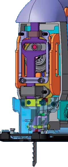
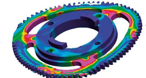
APM FEM
Designs and calculates machine elements, mechanisms, and structures, and performs general purpose strength analysis using FEM (finite element method). APM FEM includes assembly preparation tools for performing calculations, setting boundary conditions, and specifying loads. An integrated generator of finite-element meshes creates both fixed and variable-size meshes. It also includes post-processor. These functions allow it to work with solid parts and assemblies designed in KOMPAS-3D, and to analyse the behavior of models when various loads are applied, such as statics, fundamental frequencies, stability, and thermal loading..
Results of calculations include the following:
Equivalent stresses and their components, and principal stresses Linear, angular, and total displacements
Strains in model components
Maps and orthographic epures of internal forces
Contact forces within an allowed band ofcontacts
Value of safety factors, and the forms of lossof stability
Safety factors and numbers of cycles, as determined by fatigue strength, Safety factors as determined by flow and strength - Temperature fields and Therm tension
Center of gravity, weights, sizes, lengths,areas of surface, model moments of inertia, static moments, and the squares of cross-sections
Supporting forces in construction legs, and the cumulative responses adduced to the center of gravity of models
APM FEM solves the following linear problems
Intensely deformed states (static calculations)
Static stre`
ngths of assemblies
Stability
Thermoelasticity
Stationary thermal conduction
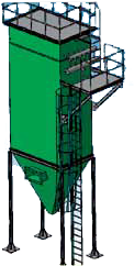
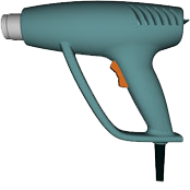
Unwrap
The Unwrap add-on automates the design of dust,gas, and air flues, pipelines, and other sheet metal parts. It automates time-consuming calculations and construction processes, and so accelerates the speed at which these drawings are created.
Works with KOMPAS-3D
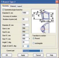
The add-on also creates unwrap drawings ofselected units with specified precision, calculates product masses, and savescoordinates of curves to text files. The following shapes can be unwrapped - Truncated cylinders
Regular, truncated, and sloped truncated cones
T-branches of different cylindrical and taperedshapes
A text file of the unwrap's contour design points can be used by CNC machines.
The Mould and Die Design
Automate the design, analysis, and construction of steel moulds used for making plastic parts from pressure castings. The add-in provides the following functions:
Analyzes 3D models - Designs the shapes of die moulds
Models the mould channeling systems
Mould and Die Design add-in is a powerful system that increases the production performance of designers, improves the quality of the design, and so enhances the competitiveness of a company's products.
TheDimensional Chain
Calculates dimension chains for drawings andfragments. Elements of a dimension chain are represented by fixed dimensions orline segments. The add-in performs calculations for horizontal, vertical, andangled dimensions; calculations can include maximum-minimum orprobability-theoretical methods.
Discrepanciesare calculated for nominal dimensions in the range of 0 – 10 000mm. Fordimension chains in which at least one nominal size does not fit into therange, only calculations of nominal values are performed.
Thefollowing tolerances are calculated: “A” “B” “C” “CD” “D” “E” “EF” “F” “FG” “G”“H” “JS” “K” “M” “N” “P” “R” “S” “T” “U” “V” “X” “Y” “Z” “ZA” “ZB” and “ZC”with an accuracy 0 to 18 decimal places. Both shafts and holes are supported.
TheDimensional Chains Calculation add-in calculates dimension chains, and findsthe right value of closing segments using a variety of calculation methods.
Cables 3D
The system Cables 3D intended to:
design 3D models of electric cables andharnesses for designing various electronic and electromechanical devices,construction design, for fire-signaling and security systems;
calculate cable and harness lengths;
calculate mass parameters for cables andharnesses;
create harnesses and cables assembly drawings;
create assembly drawings and specifications.
The system operates in the KOMPAS-3D V13 environmentor higher
e-CAD KOMPAS-3Dconverter
The eCAD–KOMPAS-3D Converter add-onimports 3D circuit board models from eCAD systems. Works with KOMPAS-3D
The converter reads data from eCAD (electronicCAD) systems in the standard IDF exchange format into KOMPAS-3D. This add-onworks specifically with P-CAD (v. 2000-2006), OrCAD (v. 9.X), andAltium Designer (previously known as Protel).
KOMPAS-Macro
The KOMPAS-Macro add-on allows you to record,replay, and store macros. Macros are drawing and editing steps that areexecuted like a single command, which allows you to design more quickly. Works with KOMPAS-3D
The macro development environment is Python, ahigh-level object-oriented programming language. To supplement Python, KOMPASincludes standard Windows API functions and KOMPAS-specific macro libraryfunctions. Macro are stored in text files.
Materials library
Material library is database of information about materialsthat are used to manufacture products. Materials Library applies physical andmechanical material properties to 3D models designed in KOMPAS-3D.
StandardParts Catalogue
The Standard Parts Catalog contains parametricparts as 3D models and 2D drawings based on DIN -ISO standards. Works with KOMPAS-3D - KOMPAS-Graphic.
The Standard Parts Catalog offers thefollowing features:
Searches standard parts with multiple variationsquickly.
Replaces parts with user defined ones . Modifies properties of standard parts in anyorder. Specifies geometric properties, such asdistance, length, diameter, corner radius, and then sets them as key properties. Bookmarks the favoriteslist of oft-used parts for quick access
Template Manager
The Template Manager creates, maintains, and re-uses customized template libraries. Works with KOMPAS-3D. Requires MicrosoftExcel or OpenOffice.org Calc.
This create a wide range of templates, and then fill them with objects andproperties as necessary. You can connect variables in the templates with tablesin a spreadsheet. Templates can be pasted into KOMPAS-3D documents as sets ofobjects, such as lines, arcs, and curves, as library macros, or as components,and then edited with the Template Manager tools. When placed as part orassemblies, they can be edited with KOMPAS-3D tools. Templates can befilled out with the user’s details, fragments, and parametric tables, andlinked to each other. One spreadsheet document can correspond to several parts,as well as to fragment files from the template library.
Trace Parts Online - Standard Parts for KOMPAS-3D
The TraceParts OnlineLibrary add-on is one of the largest mechanical part catalogs in theworld. By using parts in your drawings from this library, you greatly reducethe time it takes to complete a design. Works with KOMPAS-3D
The library consistsof more than 100 million 3D CAD models and 2D drawings. The parts are based onEuropean and other suppliers in the tooling, machinery, aerospace, automotive,and others industries. You launch Trace Parts directly from inside KOMPAS-3D Select a part, and then insert it into your assembly as a native 3D or 2D part.


