MATHEMATICAL TECHNOLOGY IN AUTOMOBILE
MATH ILLUSTRATIONS QUICKLY CREATE ACCURATE DRAWINGS FOR TEST and PRESENTATIONS
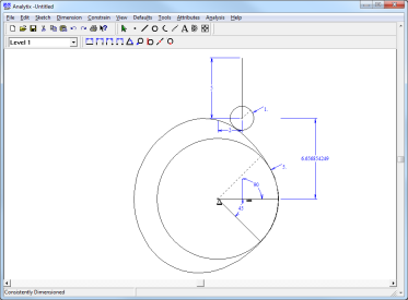
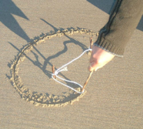
Introducing Math Illustrations, an easy intuitive way to create geometric diagrams for documents and presentations.
By combining the constraint-based architecture of Geometry Expressions with easy-to-use drawing and graphing features, Math Illustrations lets you create more effective geometry figures for your students in less time.
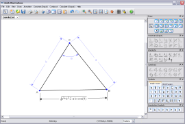
Draw Quickly:Quickly create drawings by using a constraint-based model. With a single click, add leader lines and dimension arrows to specify lengths, angles, distances and radii.
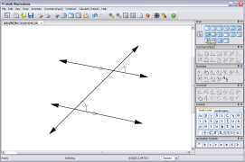
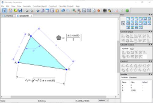
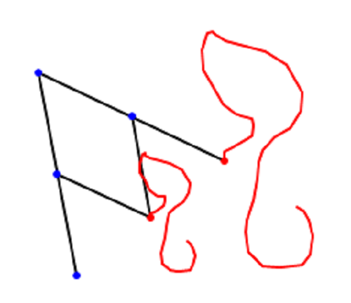
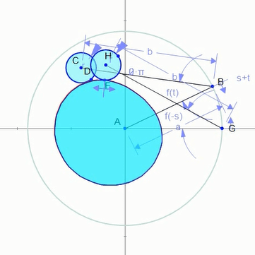
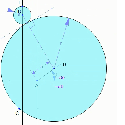
When you create a diagram in Math Illustrations you get all the symbols without any effort! When you constrain or annotate a line, the length symbols is added automatically. This is true for any annotation or constraint that you add!The Power of Constraints Plus the Flexibility of Annotations When you draw with constraints you don't have to worry about lining up shapes so they appear to have a certain relationship. If you want a line tangent to a circle, simply constrain it to be. You are then free to move or resize your circle and the line will automatically remain tangent to the circle!When you want to label an angle, length, etc without constraining its value use can use annotations. An annotation label can be anything you want -- including a mix of text and 2D math.
Draw Accurately:
You can set the lengths of lines, value of angles, and size of radii in your figures. If side A of a triangle is length 4 and side B is length 6, you can be sure that side B is 1.5 times longer than side A.
Drawing to Scale
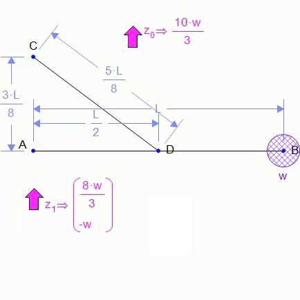
With the help of constraints, drawing figures to scale happens automatically. If line AB is constrained to a distance of 4 and line CD to a distance of 8, CD will automatically be twice as long as AB. The same is true of angles. If you want a triangle with angles 30°, 60° and 90° simply constrain two of them (the software will figure out the third).
Of course you may want to purposefully draw a figure that is not to scale. This is where the annotations come in. Using annotations instead of constraint you can set a distance or angle to be anything you want!
Export Easily:
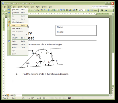
Draw a selection around your figure to place it on the clipboard in raster and vector format. Paste this directly into Word, PowerPoint, Photoshop, iWork -- you name it! We also support file export of EPS, EMF, PNG, JPG, Tiff and more.
Export to your document in 3 easy steps
Exporting to Word, PowerPoint, iWork, Paint, Photoshop, Fireworks is extremely easy in Math Illustrations. By drawing a selection box around your image both a vector graphic image and raster image is placed on your clipboard. When you paste into another program the vector image will be pasted if it is supported, otherwise the raster image will be pasted.
Here is a quick run down of the steps needed:
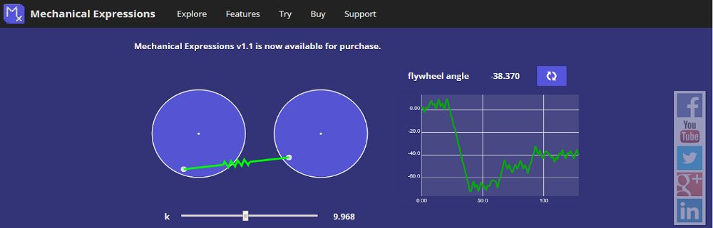
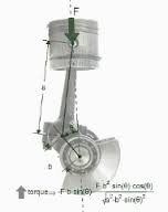
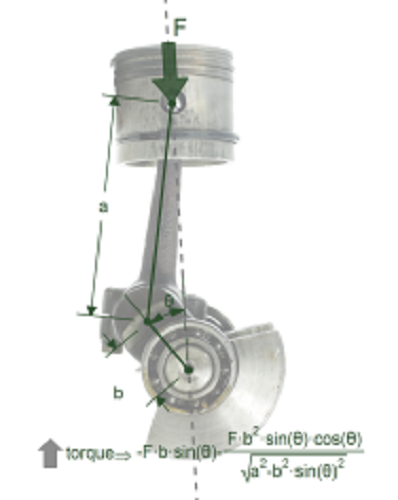
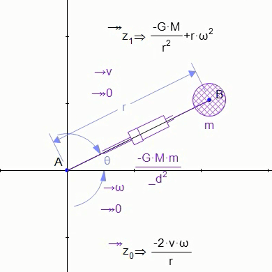
Mechanical Expressions is a symbolic mechanics program. Create a model, specify the geometry using symbolic constraints, add velocities, masses and force elements, and then extract mathematical expressions for output velocities, accelerations and forces. Copy expressions for input into a mathematics system like Mathematica, or copy them as Tex, MathML, or computer source code (in 9 languages). Or, create an HTML5/Javascript app, allowing you to communicate your design intent as an interactive, single-file web page that you can email to your colleagues or post on your web site. You'll quickly discover that Mechanical Expressions is truly a new breed of software.
The Next Generation of Mechanical Engineering Software
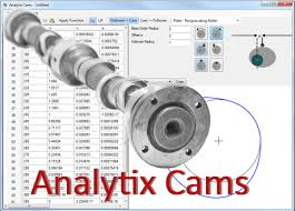
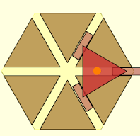
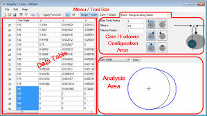
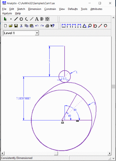
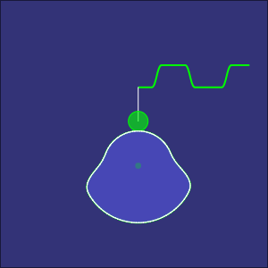
Analytix Cams enables mechanical engineers to quickly synthesize a cam profile given their follower motion requirements. Or...from an existing cam profile, the follower's geometry and kinematics can be quickly designed, fine-tuned and analyzed. With Analytix simulation software, you can optimize the cam/follower interaction with your mechanical system. Then export DXF to CAD or coordinate data to NC/CAM software.
Here's how Analytix Cams is used to synthesize a cam profile. First, you choose the cam/follower type and such things as direction of rotation and follower offset. Then select a range of cam rotation, specify the starting and ending requirements for follower displacement, and the desired curve type (such as cycloidal, dwell, or constant acceleration).Analytix/Cams then automatically synthesizes the precise points in between, taking into account all the geometry involved in that particular cam/follower configuration.
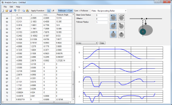
For example, you can specify that the follower angle should have a modified trapezoidal rise of 35 degrees between 0 and 90 degrees of cam rotation and so on. The advanced user always has the option of fine-tuning the data points manually (or inserting them from another source).Kinematic and other data is automatically calculated and displayed in both tabular form and graphical form: displacement, velocity, acceleration, jerk, radius of curvature and pressure angle.
Any cam profile developed in Analytix Cams can also be used inside Analytix mechanical simulation software to analyze the cam motion in combination with actuators, linkages, or other parts of a larger mechanical system.Cam design and mechanism analysis can be done quickly in an affordable, integrated solution, letting you work back from required end-effector motion to cam/follower design or vice versa.
Specifications
- Plate -- oscillating roller follower
- Plate -- oscillating flat-face follower
- Plate -- reciprocating roller follower
- Plate -- reciprocating flat-face follower
- Linear -- oscillating roller follower
- Linear -- reciprocating roller follower
- Barrel -- oscillating roller follower
- Barrel -- reciprocating roller follower
- Follower-to-cam method? YES
- Cam-to-follower method? YES
- Simulate inside larger mechanism (YES, with Analytix)
- Dwell
- Constant velocity/acceleration
- Cycloidal
- Modified Harmonic
- Modified Trapezoid
- Modified Sine
- 345-Polynomial
- 4567-Polynomial
Cam Types
Usage
- Cam profile (x-y or r-theta)
- Displacement
- Velocity
- Acceleration
- Jerk
- S-V-A-J
- Pressure angle
- Radius of curvature
- Geometry options
- Clockwise/counter-clockwise
- Left/Right
- Base circle radius/angle
- Initial angle
- Follower arm length
- Pivot-Pivot Distance/Coordinates
- Offset dimension-left/right
- Follower above/below
- Barrel radius
- Follower radius
- Data interchange
- DXF export
- X-Y or R-Theta coordinates, tab-delimited import/export
- Windows copy and paste to Excel
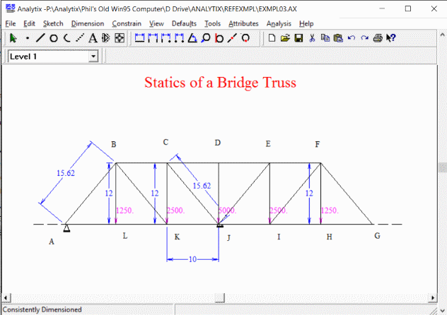
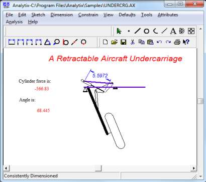
Analytix is a sophisticated mechanism design-and-analysis software package for the PC that puts you, the engineer, back in control of the creative process.
By automating tedious, error-prone number-crunching analysis and giving you the instant visual feedback you need to do something more satisfying--improve your design.
With Analytix, there's no need to enter long, involved formulas to analyze your designs. Kinematic equations are embedded in the software. So, in essence, the math is done for you. Instantly. And accurately. Full kinematic, inverse dynamic and force analysis. It even does the analysis you may not have had the time or luxury to get to. Such as a statistical or minimum/maximum tolerance stack-up on your design. Or force analysis for every possible scenario, instead of what you think (or hope) is the worst case.
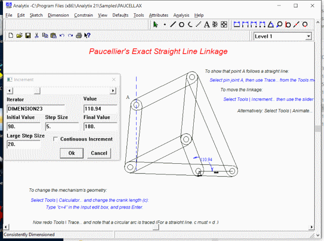
It's simple. All you have to do is quickly sketch your geometry in a functional point-to-point centerline format, use your mouse to click on a driving angle or actuator, assign values (for velocity, acceleration, masses, moments of inertia, etc.), then click on any other point or line to see resultant conditions. Your analysis is complete.
Suppose you don't get the results you'd envisioned. No problem. With Analytix, you can change any dimension on your design and get updated velocity and acceleration information automatically and instantly. Without having to reprogram or modify your equations of motion. Analytix is so quick and easy to use, you'll even have time to explore entirely new design options and still meet or beat your project schedule.
Technical Specifications
Parametric Sketching-2D
- Patented Variational Geometry engine, with auto-dimensioning
- Distance and angle values, velocities, and accelerations
- Tolerances on input distances and angles
- Applied forces and moments, springs, dampers, actuators
- Masses and moments of inertia
- Geometric position, velocity, acceleration
- Reaction forces
- Shear force and bending moments
- Stress and deflection in trusses
- Tolerance stack-up, sensitivity, trace, zones, absolute or statistical
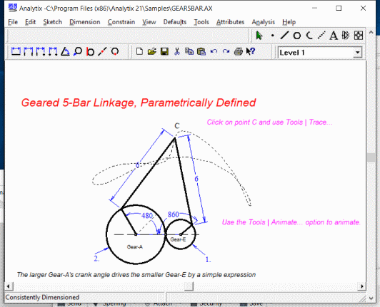
- Animation, point trace, envelope
- Equation calculator and iterative equation solver
- Graphs and tables of output parameters
- DXF input and output
- Windows Dynamic Data Exchange (DDE), Cut & Paste
- SI
- fps
- ips
- user-defined unit systems
Pentium class PC running Microsoft Windows 95 or later (tested through Windows 7/8)
8 MB available RAM, 10 MB available disk space
Mechanical Model Outputs

- If you like the free browser-based version of Geometry Expressions, you should try the full version. It's not free, but it's well worth the money, here's why.
- You can build larger more complicated models with varied styles, hidden items, and you can save the models.
- You can export mathematics in the format for a variety of different CAS systems, along with Tex and MathML.
- You can export mathematics as computer source code in a dozen different languages.
- You can create your own apps, without programming, as JavaScript or Lua apps
Explore
See how you can use Geometry Expressions for mathematical modeling, app generation and code generation.
First take a look at how constraint based geometry works, and how it enables you to generate mathematical models.
Explore
See how you can use Geometry Expressions for mathematical modeling, app generation and code generation.
First take a look at how constraint based geometry works, and how it enables you to generate mathematical models.
Apps
Our companion site Euclid's Muse contains hundreds of apps generated by Geometry Expressions.
Most of them are free for you to use on your site (with attribution)
You can even post your own apps to Euclid's Muse.
Product Family
Math Illustrations is a lite version of Geometry Expressions without the symbolic features. It is useful for illustrating mathematical problems, or for doing geometry numerically.
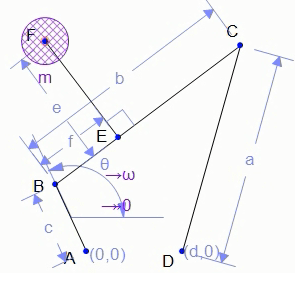
Mechanical Expressions adds physical properties such as force, mass, velocity and acceleration to you geometry model. It allows you to get symbolic results for reaction forces and equations of motion. You can even create dynamic simulations as apps.
Mechanical Expressions can model a broad array of situations pertinent to physicists and engineers. In this section, we've compiled fifteen examples that showcase Mechanical Expressions' capabilities.We've grouped these examples into five subsections:Kinematics, Statics, Inverse Dynamics, Dynamics, andGeometric Modeling. Each category contains three distinct examples: a symbolic example (often incorporating the use of a computer algebra system alongside Mechanical Expressions), a simulation (created with Mechanical Expressions' export to HTML5/Javascript App feature), and a video that shows the Mechanical Expressions workflow.
Mechanical Expressions lets you do sophisticated geometrical modeling and communicate the results as web pages or as mathematics
Use Mechanical Expressions to its Full Potential
Check out our Youtube channel for ideas and tutorials on Mechanical Expressions. Or, visit our support page for additional Mechanical Expressions resources.
THE PROGRAM IS CAREER APPLICATION IN MULTIPLE AREA TO ALL PROFESSIONAL


