Analysis of strength and stability shlambasseyna
Analysis of the strength and stability of the slime basin in the APM Civil Engineering software package
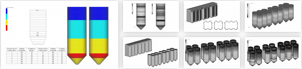
object model
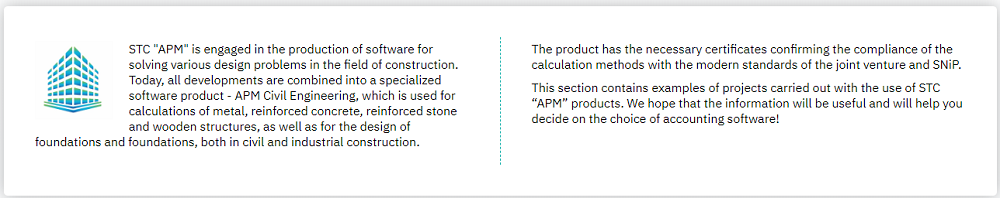
Shlambasseyn is a cylindrical construction with an internal diameter d = 8 m. The height of the cylindrical part h = 19.4 m. The height of the tapered portion shlambasseyna h = 3.7 m. The thickness of the plate varies in the range from 8 mm to 14 mm, while the thickness of the part, providing transition to the cone is 24 mm.
shlambasseynov group connected by horizontal steel profiles, the length of each of which is about 2 m. Also mounted on block shlambasseynov connecting them, steel gallery.


In the process of thickness measurements were obtained actual values shlambasseynov wall thicknesses. Identified parent metal reservoir space wall thinning to 74%.


A bearing structure carried on the guide ring shape and six columns under each shlambasseynom. The columns are arranged on a concrete platform foundation. The height of the supporting metal studs is 0.7 m.
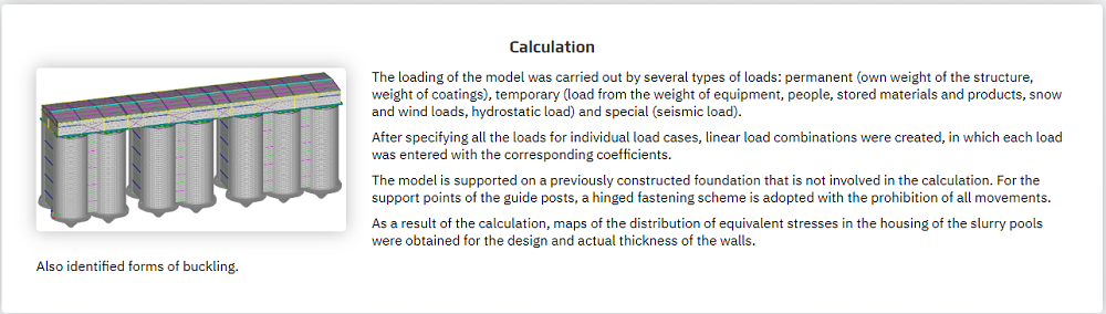
Bearing pattern formed on a foundation constructed earlier, not involved in the calculation. For GCP guide post adopted hinge fixing circuit with the prohibition of all movements along the axes OX, OY, OZ. Installation scheme supports is shown below.


Load, impact and combinations thereof
load values were set in accordance with the requirements
1. SNIP 2.01.07-85 * Loads and effects
2. Part 2 SNP - 1954 norms of building design
3. SNIP RK 2.03-30-2006 Construction in seismic areas
Uploading models performed several load types: constant (own weight of the structure, coating weight), time (the load of the weight of the equipment, the people, the stored materials and products, snow and wind loads, hydrostatic loads) and special (earthquake loading).


After all the stress on individual loadings were created linear combinations of loads to which each of the loadings entered with the corresponding coefficients.
The calculation results


