Calculation of strength of NPP pipelines
Method of calculation
The calculation is made in accordance with the requirements of the norms for calculating the strength of equipment and pipelines of nuclear power plants (PNAE G-7-002-86).
Within the verification calculation, it is necessary to perform the following types of calculations:
• calculation for static strength;
• calculation for cyclic strength;
• calculation for seismic actions.
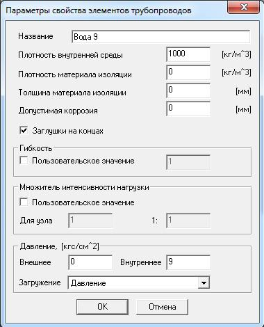
The system for performing complex engineering analysis of mechanical equipment and structures APM WinMachine allows you to build a model that reliably describes the geometry and behavior of a real structure with subsequent finite element calculation. When constructing, a special kind of rod elements is used - the pipe (Pipe), in Figure 1 the dialog for setting the properties of this element is shown. As properties, this element allows you to specify the density of the internal environment and insulation material, the thickness of the insulation layer and the permissible corrosion, as a load - internal or external pressure.
The design module APM Structure 3D, included in the software package, allows calculating the stress-strain state of the structure under static and dynamic loading, calculating stability, natural frequencies and forced oscillations, and other calculations. The calculation for seismic actions is carried out by a linear-spectral method using the spectra of horizontal and vertical accelerations. In APM Structure 3D.
The APM Structure 3D module has an attestation passport No. 330 dated April 18, 2013 issued by Rostechnadzor, as well as a certificate of compliance with such regulatory documents as SP 20.13330, SP 14.13330, SP.15.13330, SP16.13330, SP-52-101, SP-50- 101, SP-50-102.
Calculation of the NPP pipeline
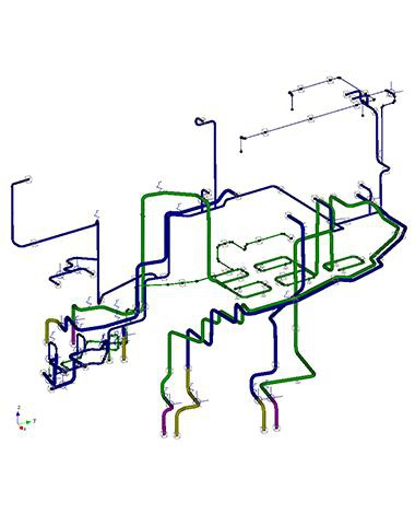
When constructing the design model of the pipeline, the final element "Pipe" was used. Figure 2 shows the finite element model of the pipeline in question.
Power boundary conditions are given in the form of the pipeline's own weight, internal pressure, and temperature along the length of the pipeline.
Kinematic boundary conditions are specified in the form of the following types of supports, placed in accordance with the execution schemes:
- rigid supports (exclude all movements and angles of rotation of the pipeline section);
- fixed supports (exclude all movements of the pipeline section);
- spring suspensions (elastic support);
- sliding supports (exclude vertical movements);
- guide legs (only allow movement along the pipeline).
The static strength of the pipeline elements, according to PNAE G-7-002-86 and RD EE 1.1.2.05.0330-2012, is checked for groups of stress categories (σ) 1 and (σ) 2 .
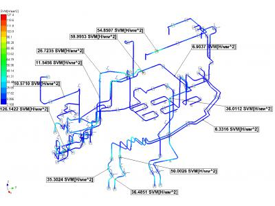
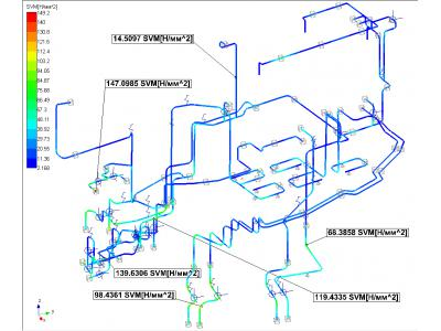
The analysis of static strength by groups of stress categories (σ) 1 and (σ) 2 is performed for pipeline elements loaded with internal pressure and self-weight. When checking the static strength by groups of stress categories (σ) RK, the range of stresses from internal pressure, self-weight and temperature stresses are taken into account.
As a result, the maps of the distribution of reduced stresses (σ) 1 and (σ) 2 (figure 3) and reduced stresses (σ) RK (figure 4) in the pipeline were obtained.
Conclusion
From the results of calculations, conclusions were drawn about the strength of the AES pipeline for various types of calculations in accordance with the requirements of the standards of PNAE G-7-002-86 and RD EE 1.1.2.05.0330-2012.
The results show that the system for performing complex engineering analysis of mechanical equipment and structures APM WinMachine can be used for pipeline calculations.


