APM WINMACHINE FEATURES
ANALSIS APM STUDIO APM STRUCTURE 3D APM SHAFT
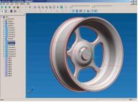
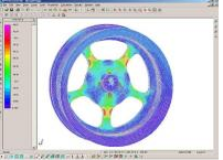
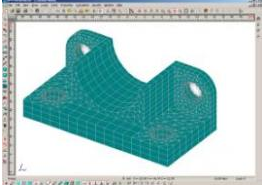
APM Studio – 3D objectspre-and-post processor for finite element analysis. APM Studio is pre-and-postprocessor for finite element analysis of surface and solid models with STEPfile support. It is one of the APM WinMachine basic tools. The module includesbuilt-in finite element mesh generators with different options. It performsstatic, buckling, modal and heat analysis of parts and assemblies.
APM Studio
APM Studio is pre-and-post processor for finite element analysis of surface andsolid models with STEP file support. It is one of the APM WinMachine basictools. The module includes built-in finite element mesh generators withdifferent options. It performs static, buckling, modal and heat analysis ofparts and assemblies.
Module purposeModeling of objectsstructure in order to develop working design plans and specifications.Computer-aided generationof the finite element mesh on created models and further import of thesemodels into APM Structure3D to analyze deflected mode under the influenceof various load-bearing factors.
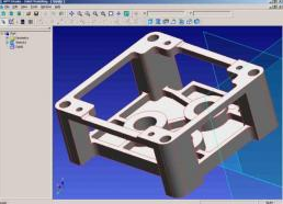
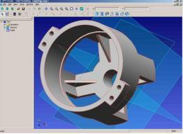
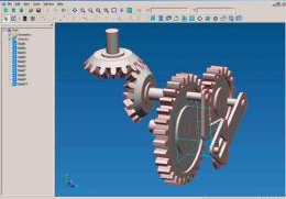
Modeling in APM StudioOperation in APM Studio finally results in surface and solid-state objects,created by means of 3D modeling function.
One of the basic solid modeling objects is a sketch. The sketch can be oneof orthogonal coordinate planes or an arbitrary plane in space. All 2D drawingsare fulfilled as a sketch. In this case the following functions are used:drawing of lines, circles, arcs, polygons, setting fillets and bevels-truncation, aligning along the border, displacement, copying, moving,mirroring, creating arrays — rectangular and circular, rotation of objects etc.
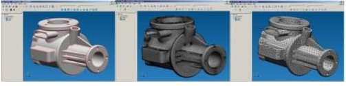
Data can be transferred into the sketch from external graphics editors, bymeans of its import from *.dxf, *.agr file formats. Export of geometry from thesketch to 2D APM Graph editor is also possible. 3D models are imported to APM Studio via the exchange STEP format. Furtheryou can change its and prepare for assessment of the stress-strained state.
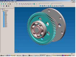
Surface modeling - Surfaces are created by means of operations on 2D curves, prepared insketches. APM Studio makes it possible to form surfaces by followinginstructions sphere-extrusion along the normal and arbitrary curve-rotation-contour plane etc. Curved surfaces can be defined by a set of arbitrarycross-sections. To create more complex surfaces, the following operations with finishedsurfaces can be used: intersection-fillet-setting bevels-sewing of surfaces=removing existing edges. Solid-state modeling - Solid-state bodies are created by means of extrusion, rotation, torsionetc. carried out on 2D objects prepared in sketches. To create complex modelsit is necessary to select one of the following operation: unification,subtraction or intersection. Therefore, the model on the screen will be resultof the selected operation’s type on the existing and newly created object.; APM Studio interface
The front-end interface of APM Studio can be divided into five regions: amain menu, a working window, a toolbox, an operations tree window and a statusline. These areas can be arranged by the user on the screen to his discretion. Operations tree All objects created by the user in APM Studio are reflected in theoperations tree. The root of the operations tree is a Part. The first elementof the operations tree is the Geometry node. It contains the coordinate planes,which can be chosen as the sketch planes. Further the objects are following:sketches, curves, surfaces, solid bodies. Every surface or a solid body drawnin APM Studio is designated with a node in the operations tree. When in thechoice mode, required elements can be chosen from the operations tree and thefollowing operations with them can be performed: deletion, modification etc. Viewport The viewport is a main window for modification and viewing operations,performed in APM Studio. Global orthogonal coordinate system is introduced fororientation of objects in space. The viewport has two modes- the sketch editing mode and the surface editingmode, as well as of solid bodies.
Shortcuts
When working with APM Studio several operations are called most often andsometimes it is not convenient to access them via menu or toolbar. Editingenvironment of APM Studio contains speed buttons, called by means of the mouseand keyboard keys, which are necessary to move and rotate view as well as fordynamic zooming.
When creating some curve it is possible to call an object snapping which isnecessary for this specific matter. It is called a local snap.
The system of context menu is developed rather widely for different casesof objects editing.
Connection with APM Structure3D
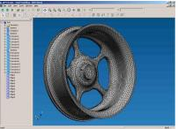
As it was mentioned above, APM Studio represents also a powerful tool forcreation of objects for the finite element analysis in APM Structure3D. Thespecial mode is provided in the module – “Finite element analysis”. In thismode the operation is carried out with the model itself, but not with the finalelement mesh, which undoubtedly is a positive factor simplifying performance ofthe required operations. Directly in the viewport the model can be arbitrarysecured and loaded both by force and by thermal effect.
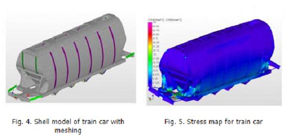
Further to create the finite element representation of an object in APMStudio, there is the function of the finite element mesh generation. Whencalling it corresponding fragmentation of the object with preset step isperformed. If there are complicated and non-uniform geometric transitions inthe designed model, so-called non-adaptive fragmentation can be carried out. Inthis case the program itself varies the fragmentation step value to improve thequality of the design result. APM Structure3D permits to import the 3D modelcreated and divided into the finite elements, to prepare it for calculation (toset materials etc.) and to carry out the design for the purpose of determiningthe stress-strained state or temperature fields.
APM STRUCTURE 3D
APM Structure3D is intended for complex analysis of 3D structures and parts. It canbe used for calculations of rods, plates, shells and volumetric solid-state structures,as well as their arbitrary combinations.
APM Structure3D
APM Structure3D is intended for complex analysis of 3D structures and parts. It can be used for calculations of rods, plates, shells and volumetric solid-state structures, as well as their arbitrary combinations. Therefore, there is a possibility of calculation of various building and mechanical engineering structures and theircomponents. The complex analysis is comprehended as stress-strain analysis of the above–mentioned objects of arbitrary geometry with arbitrary loading conditions and constraints, as well as a number of other calculations.
APM Structure 3D possibilities
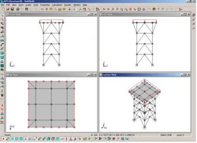
APM Structure 3D has built-in pre-processor for model preparation. Structures and their components can be either created in graphical editor or imported using the DXF file format from 2D and 3D graphics editors or directly via APM Studio with prepared finite element mesh, loading conditions and constraints. Results are presented in convenient way and can be viewed using post-processing tools included.
APM Structure 3Dcan perform various types of calculations, including:
Linear static analysis - Non-linear staticanalysis - Buckling analysis
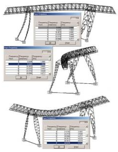
Thermal analysis - Modal analysis - Dynamic analysis - Steel design
Calculation methods
All calculations are performed using finite-element method. Application includes large library with rod, beam, cable, shell and solid elements. Other methods of structural mechanics appropriate to the above-mentioned problems are also used. Finite element number for rod sections meshing and, hence, the duration of calculationis user-specified parameter. By default the program provides typical settings for the majority of design cases. Total number of finite elements is limitedonly by capabilities of the user’s hardware.
Model meshing isperformed in semi-automatic mode and corrections can be made by manual editing. Several types of element validity checking are available.
Specializedinterface
A modern special-purpose interface is provided in the module for efficient fulfillment of design and graphic procedures. It includes:
3D graphical pre-processor for editing structures and machine parts as combinations from beam, plate and solid elements, including tools for loads and constraints definition - visual tools for 3D model representation - 2D graphical sections editor for rod/beam elements
post-processor tools for calculation results processing
The types of loads can be applied to components of the structure:
concentrated force or moment (at node or at arbitrary point of the rod)
load distributionalong the rod length (axial force, transversal force, distributed torsionmoment) - loads caused by displacement of supports - normal disributedforce affecting the plate - wind and snowloads acting on plate elements - as well as seismic loads (according to theBuilding Regulations) - temperature effects on any component of the structure Possibility ofoperation with different loadings of the structure and their combinations has been realized.
Databases APM Structure3D includes standard rolled section library and material databases. The specialized section editor provides possibility to create arbitrarynon-standard sections including multiply connected ones as well as to edit the existing ones. After that all section properties are calculated automatically,including torsion moment of inertia. Import of section from an external graphics editor, which has a possibility of creating files in DXF file formatis also available.
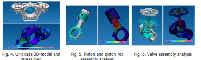
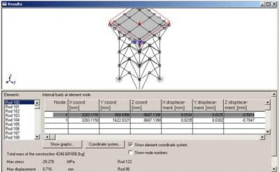
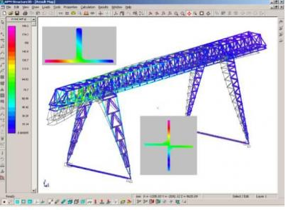
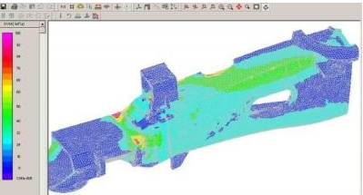
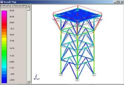
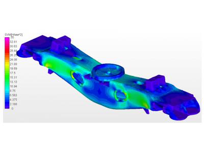
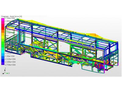
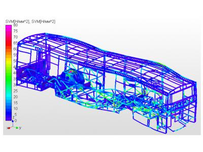
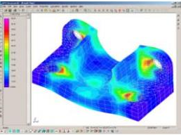
APM Structure3D can perform calculation of stress and strain values in any point of the structure, taking into consideration the external loading and weight of every component. Calculation of rod elements is carried out accounting all stress concentrations, which leads to more exact values of effective stresses.Besides, there is a possibility of setting an eccentric connection of rods inthe structure, as well as automatic determining of weight of the whole structure. APM Structure 3D allows to determine internal loads within every finite element. This information can be used for further calculation of welded,threaded joints or riveted joints. Results of calculations by means ofspecialized visual tools are presented in color, in the form of contour lines,or in the form of diagrams of stress, moment, load-bearings, strains etc.
The interfaceincludes visual tools of:
deformed state ofthe model - stress distribution at any current section of any rod component - stresses and displacements (linear and angular) at node points - diagrams of bendingand torsion moments, stresses and strains, transversal forces, etc,distribution along the length of any rod being a part of the construction - stresses can be obtained both in the form of equivalent and separate component - displacement mapcan be represented both as resultant or summary and as its component valuesalong different datum lines - distribution ofthermal fields
Post-processing tools allows printing and saving in RTF file format all results obtained, which makes report composition more convenient.
For convenience,in pre-processing stage structure can be represented as wireframe, thin plateor solid model (with consideration of cross-section types and positions). When operating with the module it is possible to use layers and to performcalculations on parts of the structure. APM Structure3D has detailed and easy-to-use help and documentation system.
A wide spectrum of the above-mentioned possibilities, provided by APM Structure 3D permits to improve significantly the design quality of lengthy objects and to reduce the design period, as well as to decrease considerably weight of the structure and,hence, to cut it’s cost. By means of APM Structure3D it is possible to designstructures, close to full-strength ones according to strength, rigidity and vibration activity criteria and, therefore, meeting the customer’s requirements best.
The forced oscillations mode is set as a law of changing load with time using the built-inspecialized editor. Calculation of forced oscillations permits to obtain stress and strain maps in real-time operation mode. Review of the stress maps is carried out in the animation mode. The mode of spatial truss structures calculation has been realized. In this case the framed structure can be transformed into the truss one and vice-versa.
Based on theresults of the calculation, APM Structure3D can be used to select necessary sections from the selected library, which satisfy strength and stabilityconditions for a given structure.
APM Shaft
APM Shaft let to perform the complete design cycle starting with shaft geometryspecifying and finishing with the complete static and dynamic calculation aswell as drawing generation.
APM Shaft Shafts areoperating as support of rotating parts and transmit rotation moments. They areregarded as one of the main machine elements; thus strong requirements aremaded to the manufacturing precision, durability, stiffness, steadiness andvibrations of shafts. APM Shaft let to perform the complete design cyclestarting with shaft geometry specifying and finishing with the complete staticand dynamic calculation as well as drawing generation.
Main Features Static strength calculation - Fatigue calculation - Dynamic calculation - Working drawings generation
APM Shaft represents software for calculation and design of the shafts and axes.
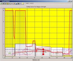
With APM Shaft you can calculate reactions in the shaft supports - diagrams of bending moments and angles of bending - diagrams of torsion moments and torsion angles - strained state of the shaft - stress state under static load - fatigue safety factor - diagrams of lateral force
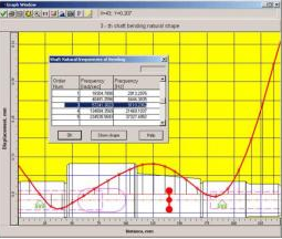
natural frequency and natural shapes of the shaft. You can save results of calculation as file with *.wsh extension (APM Shaft format), or as file with *.rtf extension (use MS Word for edition it).
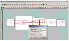
Graphic editor APM Shaft has special graphic editor for setting shafts and axes geometry. The editor puts at user disposal flexible and convenient methods provided for specifying shaft geometry - specifying loadsacting on shaft- placing shaft supports
The main featureof APM Shaft graphic editor is the special set of primitive elements, which itdeals with. The primitive elements of APM Shaft are the basic elements of the shaft geometry (cylindrical and conical parts, chamfers, fillets, grooves,holes, parts with threads, keys, splines, etc.) as well as loads that can acton shaft or supports. Such approach simplifies significantly input and editingof geometry of the shaft and of other data required for calculation.
Calculation methods and criteria Strained and displaced state of the shaft is calculated by methods of materials resistance.The static strength is evaluated by the effective stresses, obtained by means of the energy method. Dynamic responses such as natural frequencies and natural shapes are determined by finite element method.
The calculation of fatigue strength is reduced to the safety factordetermination in the current shaft section both for the constant external loadand for variable in time load (according to the arbitrary law).
Working drawingsgeneration
In the APM Shaft you can generate working drawing of the transmission elements you have designed. APM Shaft provides you with the convenient dialog tools for making these operations. Using APM Graph you can make any additions and corrections tothe generated drawing, print it out and save it in DXF file format. (In orderto edits it in other graphics systems).
Database The unique mechanical database APM MechanicalData and material database APM MaterialData are part of the APM WinMachine system. All the necessary parameters such as shaft material, standard keys and splines dimensions can be taken from these data bases.