
- upgrade ArCADia-START 5 EN to ArCADia LT 10 EN
- upgrade ArCADia-ArCHITECTURE 6 EN to ArCADia-ArCHITECTURE 8 EN
- ArCADia-IFC EN
What is ArCADia LT 10?
ArCADia LT is a fully functional, easy-to-operate and intuitive CAD program that allows object-oriented creation of 2D building documentation and saving files to the 2013 DWG format. It is a basic graphic design tool for the construction industry in its broadest sense.
Basic tools of the ArCADia BIM system:
COMPARING DOCUMENTS:
- This ArCADia tool enables the user to compare designs created in the ArCADia BIM system and to find the differences between them.
MERGING DOCUMENTS:
- This tool allows to include multiple designs of various installations in one document.
MANAGING A DRAWING OF A BUILDING:
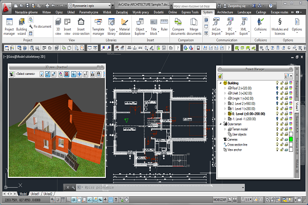
- The management of views and displayed information using the comprehensive Project Manager tree.
- The automatically created 3D view is available in a separate window to allow a presentation of the entire body of the building or e.g. a part of a level.
INSERTING:
- Elements like walls, windows, doors, etc., are now inserted with the use of the intelligent tracking function.
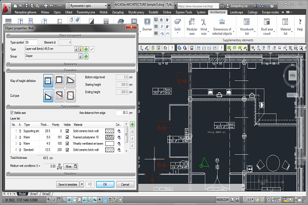
WALLS:
- Selecting walls from defined types or setting of any specified composite walls.
- A built-in catalogue of building materials that is based on the PN-EN 6946 and PN-EN 12524 standards.
- Inserting virtual walls that are invisible in the 3D preview or cross-section. They divide the room space in order to distinguish an open-space function, for example.
- Heat transfer coefficient is calculated automatically on the base of the materials selected for the space dividers (walls, ceilings, roof).
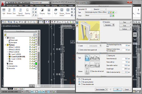
WINDOWS AND DOORS:
- Inserting windows and doors by means of parameters from the program library and creating user-defined windows and doors.
- The possibility to define the windowsill protrusion inside and outside a room, as well as its thickness.
- The possibility to switch off a windowsill.
CEILINGS
- Automatic insertion of floors (according to a level outline).
ArCADia-TERIVA CEILINGS:
- The module is used to prepare drawings for structural systems of Teriva ceilings. Drawings include all the main elements of the system: ceiling beams, transverse beams, hidden beams, trimmers, KZE and KWE ring fittings, KZN and KWN lintel elements, support grids and additionally all necessary lists of materials covering listed elements, supplemented with the reinforced steel and monolithic concrete required to create a ceiling.
- Automatic and manual calculation of all Teriva ceilings (4.0/1; 4.0/2; 4.0/3; 6.0; 8.0) in the ceiling areas of any shape.
- Automatic distribution of beams, transverse beams and ring beams on internal and external walls and on main beams.
- Automatic setting of a system of trimmers for openings and beams for partition walls.
- Automatic solving of a side ceiling access to a wall.
- Automatic calculation and setting of the required plane and offset grids.
ROOMS:
- Automatic creation of rooms from closed outlines of walls and virtual walls.
- Temperatures and lighting requirements are automatically assigned to rooms, depending on their names.
- The possibility to change the graphic imaging of a room in the view, e.g. by filling or colour.
BINDING JOISTS:
- Inserting binding joists, including reinforcements defined both for bars and stirrups.
COLUMNS:
- Insertion of columns of rectangular and elliptical cross-section.
CHIMNEYS:
- The insertion of single chimney openings or chimney shafts (groups of chimneys with a set number of columns and lines).
- The possibility to insert chimney ducts or mark the outlet of existing chimneys.
- New chimney profiles.
STAIRS:
- Defining one- and multi-flight stairs and winder stairs in any plan.
- New types of stairs: monolithic with treads or see-through with stringers. The possibility to choose the type and elements of a step.
TERRAIN:
- Automatic creation of a terrain model on the basis of spot heights from digital DWG maps.
- Insertion of a terrain plane using spot heights or lines.
- The insertion of objects that simulate elements of a network or objects existing on the terrain to check for collisions in the design.
3D VIEW:
- Inserting and modifying camera settings, from the point of view of an observer, which can be used to view a design or to save a view.
- The current scene can be saved to a file in BMP, JPG or PNG formats.
.png)
AUXILIARY ELEMENTS:
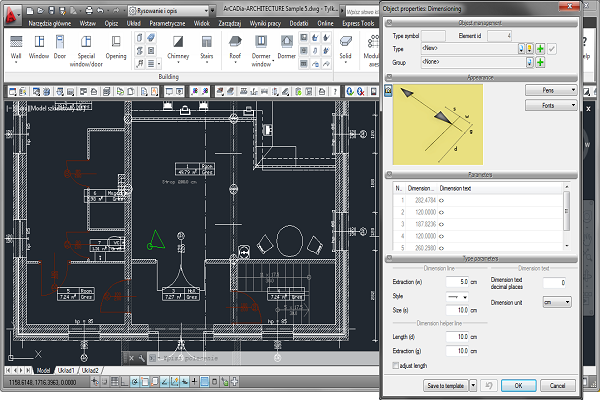
- Dimensioning:
- The automatic dimensioning of the entire floor plan by selecting dimensioning lines (total external, external for protruding elements, rooms and walls, windows and frames, as well as openings).
- The assignment of dimensioning to objects, which enables automatic modification for all edits.
- The angular and radial dimensioning of walls.
- Dimensioning that indicates arch wall lengths.
- The possibility to insert a spot height in the floor plan and cross-section.
- The possibility to insert an element description (roof, floor, wall) both in the plan and cross-section. (Apart from the match, a flag with a bill of materials for an indicated element is also available)
- Listings:
- Automatically created listings of timber for timber structures inserted in the R3D3-Rama 3D program.
- Area and cubic capacity count. New bills that automatically add up the surfaces of: gross covered area, net and gross storey and building surfaces, as well as the cubic volume. The bills also include: the minimum plot area and roof data: inclination and ridge height.
- New bill of roof surface, in which the lengths of eaves, corners, roof valleys, ridges and roof edges will also be included, apart from the roof outlay and calculations of roof slopes.
- Automatic bill of roof accessories: lengths of gutters, ridge tiles and drainpipes, the number of caps and connectors for pipes and ridge tiles, as well as the number of cowls and snow guards. The possibility to choose which elements will be included in the bill.
- A bill of roof materials.
- Wind Rose:
- The symbol and direction of the north point can be inserted on the ground floor plan.
- Communication with other systems:
- Object-oriented import and export of designs in the IFC format.
- Object-oriented data exchange with the ArCon program (two-directional transfer of an entire building solid).
What is ArCADia-IFC?
The program enables the user to import IFC files (e.g. from Revit and ArchiCAD) to the ArCADia BIM system as well as to export an architectural design along with the installations and networks, in the IFC format.
The program allows to import the body of a building in the IFC format (e.g. from Revit and ArchiCAD) while transforming objects (walls, ceilings) into elements of the ArCADia BIM system. When a design, with the installations and outer networks, is imported, elements of these installations are loaded as 3D objects with the information about their properties. The program exports ArCADia BIM system designs in the IFC format through exporting the body of a building with the installations and outer networks.
If a design has been created and exported correctly, the objects that are imported from an IFC file will be converted into elements of the ArCADia BIM system or into 3D objects with the information about their properties. If the objects do not comply with the assumptions of the system (e.g. all ceilings from all levels have been created on one level), they might not be loaded when imported.
System requirements:
- Pentium-class computer (Intel Core i5 recommended)
- 2 GB RAM minimum (8 GB recommended)
- About 3 GB free hard disc space for installation
- A graphics card compatible with DirectX 9.0 (a 1GB RAM card recommended)
- OS: Windows 10 or Windows 8 or Windows 7
AUXILIARY ELEMENTS:
MODULAR AXES:
- The possibility to insert a grid of modular axes, including complete editing options.
TITLE BLOCKS:
- Creating user-defined title blocks in the dialogue window or using graphic field editing options.
- The insertion of automatic (taken from a design) or user-defined texts into a title block.
- Saving title blocks to the project or program library.
TEMPLATES:
- Saving user-defined settings of elements (markers, fonts, default types, heights, etc.).
- The Type Manager is used to manage types used in a document and existing in the global library. From now on, it can be saved in templates which object types will be used.
LAYOUTS:
- Groups of elements of various types can be saved into a single type. All connections, sizes of elements and other individual element parameters can be saved into a single layout that can be used in future projects. The layout can be further divided to modify individual group elements.
TYPE LIBRARY:
- A built-in type library for all elements of each module.
- Library modification during the design by saving the created types.
- Library modification in the library window by adding, editing and deleting types from the global/user’s library or the project library.
DIMENSIONING:
- The arbitrary linear and angular dimensioning of a design.
LISTINGS:
- Automatically created listings of rooms for each level.
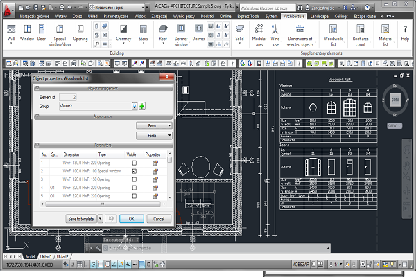
- Automatically created listings of windows and doors, including symbols.
- Listings can be exported to an RTF file and to a CSV file (spreadsheet).
- Communicating with other systems.
- Projects can be exported in the XML format.
- The possibility to edit and correct listings before they are saved. Printing listings and adding e.g. a logo.
- A new word processor called ArCADia-TEXT is available. It is launched when exporting to an RTF file.
- ArCADia-TEXT saves to the following formats: RTF, DOC, DOCX, TXT and PDF.
OBJECTS:
- An integrated library of elements allows a drawings to be detailed with the required architectural 2D symbols.
- A library of 3D objects allows created interiors to be arranged.
- The object catalogue can be extended with new libraries.
- User-defined objects created with 2D elements can be saved in the program library.
- 2D and 3D objects can be inserted with an angle with respect to the X-axis given during insertion.
- The possibility to rotate objects about the X and Y axes and to change a symbol in a view when necessary.
COLLISIONS (automatic detection of collisions and intersections between elements of the ArCADia BIM system):
- Collisions of any elements in the ArCADia BIM system can be freely listed.
- Clear lists of collisions in the project and point indicators in the plan and 3D view are available.
GRAPHIC ENGINE
ArCADia LT enables the user to draw and edit 2D documents, load raster images (e.g. geodetic maps), describe drawings using TrueType or SHX fonts, insert blocks from other documents, as well as print the documentation in an intuitive way.
POSSIBILITIES OF THE PROGRAM:
The intuitive interface enables to work in coordinates or to insert data using lengths and angles. The command bar changes in various stages of the drawing and modification process and it offers the auxiliary options that are the most useful at the moment. Selecting functions that are the most important for drawing has enabled to implement options in an orderly and simple way. Additionally, the most important tools (switching on and off the grid, Ortho, entity snaps, Project Manager and the 3D view window, interface theme modifications) have been put at the bottom of the screen, which makes both the communication with the program and the work itself easier and faster.
DRAWING:
- Drawing any elements using lines, polylines, circles, arcs, ellipses, regular polygons and rectangles.
- Editing drawing elements by means of the following tools: Move, Copy, Scale, Rotate, Mirror, Array, Trim, Explode and Offset. The user selects the item to be changed and then indicates the function to be performed.
- Closed outlines: circles, polygons and rectangles can be freely hatched using a pattern indicated in the element properties window.
- Creating and saving blocks – groups of elements that form a given symbol. A block is saved in a new document and it can be inserted both in the drawing it was created in and in any other drawing. Each time a block is inserted, the program asks about the possible scaling and rotating it.
- The description of drawings is created using a multi-line text with SHX and TrueType fonts. The text is inserted in an additional window that is displayed after the options are enabled. Its size, a font type, justification and other similar elements are defined in the Multiline Text window.
- It is possible to insert bitmap base maps in popular formats such as JPG, BMP, TIF and PNG. The following tools are available here: scale, trim, change lightness, contrast and fade.
PRINTING:
- The print sheet is put in the drawing area by default. In a clear and simple way, it shows what the printout will look like.
- The size of the print sheet and the scale of the printout can be defined in an intuitive way.
- Program options are expanded by the basic functions of the ArCADia BIM system, or smart objects creating models of buildings that are constructed of the options of the consecutive industry-specific modules.
ArCADiasoft is a member of the ITC. Some IntelliCAD 8 source codes have been used in the program.
What is ArCADia-ARCHITECTURE 8?
ArCADia-ARCHITECTURE is an industry-specific module of the ArCADia BIM system, based on the ideology of Building Information Modeling (BIM). The program can be used to create professional architectural documentation. Above all, it is intended for architects and all who shape and restore building forms.
ArCADia-ARCHITECTURE is used for the object-oriented creation of professional architectural plans and sections, interactive 3D previews and realistic visualisation. The program features specialist architectural functions, such as: automatic cross-sections, automatic dimensioning or importing object shapes from other programs.
WALLS:
- The insertion of arch, single- and multi-layer walls.
- The possibility to transform a 2D drawing created from polylines or lines into the plan of single- or multi-layer walls, virtual walls or a foundation plan.
SCRIPT WINDOWS AND DOORS:
- The insertion of windows of various shapes (circular, triangular, with an arch, etc.), including the possibility to set horizontal and vertical division and define the visibility of windowsills or cut an opening itself (without a windowsill) in a wall in the shape of special windows (doors).
- The insertion of single and double arched doors, including additional side or top lighting.
WALL OPENINGS:
- The insertion of an opening of a set width and height in a wall from the left and right side (insertion at any height).
- The possibility to insert a recess of a predetermined depth.
FLOORS:
- The insertion of any floor by indicating its shape.
- The insertion of a floor on ground in rooms of the lowest level.
COLUMNS:
- The insertion of rectangular and elliptic steel columns.
STEEL COLUMNS:
- The insertion of a vertical steel column of given dimensions and cross-section.
- The insertion of a horizontal steel object.
- The insertion of an inclined steel object.
STAIRS:
- The creation of a spiral staircase inserted with or without a pillar.
- The insertion of single ramps or ramps with a landing.
ROOFS:
- The automatic and free insertion of pitched roofs, including a complete range of modification options (changing into a single-sloped or double-sloped roof, changing the height of a knee wall and inclination of any slope separately).
- The insertion of windows and openings in the roof.
- The insertion of dormer roofs (dormer windows).
- The insertion of a timber structure from the R3D3-Frame 3D program (roof slopes exported to R3D3-Frame 3D are structurally calculated, while the roof framework is returned to ArCADia-ARCHITECTURE).
- The insertion of roof hatches.
- Automatic or manual insertion of roof gutters.
- The insertion of drain pipes which automatically detect the gutter and the level of the terrain.
- Automatic or manual insertion of ridge tiles.
- The insertion of chimney cowls, ventilation cowls and fume cowls.
- The insertion of snow guards: snow fences, snow crushers and stoppers.
FOUNDATIONS:
- The insertion of a strip footing or any defined spot footing in the plan.
SOLID:
- Drawing any shape of a solid with a set height. The solid can be further used as a terrace, platform, mezzanine, and similar elements.
- The insertion of a solid of a specified width and height, e.g. as binding joists and beams, including the possibility to select an insertion axis or edge.
- Solids are inserted through a rectangular outline.
- Edition of solids by dividing them and creating any holes.
OBJECTS:
- Importing objects in the following formats: 3DS, aco and o2c.
- User-defined symbols (2D elements) can be saved in the program library.
- A project package, which is the possibility of moving the project with imported objects to a computer where the standard object library doesn’t contain these objects.
CROSS-SECTION:
- The automatic creation of a cross-section by indicating the cut line of a building, including the possibility to define elements visible in the cross-section.
- The insertion of a stepped cross-section with any number of folds.
- The automatic insertion of ring beams, locating them above the load-carrying layer of a wall (with set types of wall layers) in the floor void.
- Lintels visible in the cross-section are automatically inserted with the window and door joinery.
- The cross-section can be automatically and manually refreshed to accelerate the work over the design.
- Views can be exploded, maintaining element groups and support for the Project Manager.
RENDERING:
- Materials for each element with its properties are defined.
- Simple (fast and easy to use) or advanced rendering, including the possibility to define all necessary settings (lighting type and position, shadow softening, etc.).
- The new rendering method for outdoors and indoors Photon mapping).
- Two renderings can be calculated in different views: daylight and nighttime views.
- The rendering window is independent of the ArCADia-ARCHITECTURE program, which makes it possible to continue working on a design, as the visualisation is calculated.
- Multi-rendering, which is recording the views from predefined cameras.


