UM Control
UM Control
Introduction UM Matlab Import, UM CoSimulation, UM User's Defined Routines and UM Block Editor - UM Matlab Import - UM CoSimulation - UM User,s Defined Routines - UM Block Editor
Introduction
UM Control module unites the following tools that combine mechanical models prepared with the help of Universal Mechanism and users libraries or Matlab/Simulink models: UM Matlab Import, UM CoSimulation, UM User's Defined Routines and UM Block Editor. During the modeling real technical systems the problem of combination of the mechanical part with parts of different kinds (automatic control, electrical machines and fields, hydraulics etc.) arises.
Such complex systems cannot be described by UM built-in tools and should be described with the help of Matlab/Simulink or dynamic-linked library (DLL) developed by user with the help of any programming language. Thereby, all tools from UM Control help us, firstly, to enlarge the range of systems that can be simulated within UM and, secondly, to simulate complex electromechanical systems like electric locomotive or car control systems (ABS, brake assist, electronic stability control and other mechatronic systems.
Considered tools have similar user interface and use the same terms that is why they all are incorporate with one module. However the tools are independent and can be purchased and used separately.
Let us consider the mentioned tools in details:
UM CoSimulaiton; - UM User's Defined Routines; - UM Block Editor. - - Getting Started: Matlab/Simulink interface; - UM Matlab Import; - See also:
UM Matlab Import
During the modeling real technical systems the problem of combination of the mechanical part with parts of different kinds (automatic control, electrical machines, hydraulics etc.) arises. The Matlab/Simulink environment is the most popular tool for technical computing. Universal Mechanism includes UM Control module, which provides interface between Universal Mechanism and Matlab/Simulink. The user can compile his/her own Matlab/Simulink model and attach it into the Universal Mechanism. Matlab/Simulink interface gives the user a possibility to include unlimited number of Matlab/Simulink libraries and interactively turn on/off interfaces.
Simulation of mechanical systems with imported Matlab/Simulink models supposes the following steps to be done.
- Creating the model of a control scheme in Matlab/Simulink.
- Exporting the created model from Matlab/Simulink as a Dynamic-Loaded Library (DLL).
- Creating the model of a mechanical system in Universal Mechanism (UM Input program).
- Loading created UM-model in the UM Simulation, importing Matlab/Simulink DLL into an UM-
model and setting connection between a mechanical part and a control scheme with the help of Matlab/Simulink interface wizard.
- Simulating dynamics of the obtained model.
See also: 1. Getting started: using Matlab/Simulink interface
Example 1. Stabilization of the inverted pendulum: UM Matlab Impor
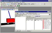
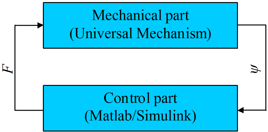
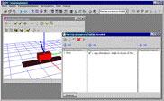
The model of the inverted pendulum is shown below. The model consists of a cart of mass M and a pendulum of mass m and moment of inertia I. The control scheme has one input - phi angle (deviation of the pendulum from the vertical position) and one output - F force, which should be applied to the cart to keep the pendulum in the inverted position.
The Matlab/Simulink model of the control for the inverted pendulum (so called PID controller) is shown in the picture below. It is necessary to include "IN" and "OUT" components into the model. These components are used for future connection of the Matlab/Simulink model with UM-model. In the model of the inverted pendulum we have the only input (pendulum angle from vertical) and output (force that acts on the cart).

Example 2. Electromechanical model of a locomotive
The model of the yard locomotive is shown below. Traction DC motors with the automatic control are modeled in the Matlab/Simulink environment and then are added to the mechanical part of the locomotive. Integration of the mechanical and electrical parts gives us full electromechanical model of the locomotive. The model gives possibilities to determine processes (vibrations) in a power train, traction torques for start-up and steady state motion, skid control, etc. The angular velocity of the rotor is the input data for the model of the DC motor, traction electromagnetic torque is applied to the rotor (from the Matlab/Simulink model of the motor).
UM CoSimulation
The CoSimulation tool from the UM Control module helps you to export a UM model from UM for posterior integration into Matlab/Simulink model. To import UM models into Matlab/Simulink you need to use so-called S-Functions, that in fact provide data exchange between Matlab/Simulink and UM models.
S-Function generally has several input and output signals, as well as several parameters. Input signals of an S-Function are assigned with UM model parameters that usually describe control forces or torques (control action). So UM model gets control forces that are calculated at the Matlab/Simulink side according to control algorithms. Output signals of the S-Function are assigned with UM variables that are created with the help of Wizard of variables and usually refer to kinematics of a UM model. S-Function parameters are assigned with UM parameters that are assigned in the beginning of a numerical experiment and are not changed during the simulation process, for example it could be inertia and geometry parameters, stiffness and damping coefficients and so on.
Simulation of Matlab/Simulink models with imported UM models supposes the following steps to be done.
- Creating a Matlab/Simulink model.
- Including an S-function element, that will be treated as a mechanical model, into the
Matlab/Simulink model.
- Loading the prepared model in UM Simulation. Setting connection between a mechanical part and a control scheme via parameters and variables. Generating the m-file.
- Simulation of dynamics of the complex model under Matlab/Simulink environment.
- Creating a model of mechanical system in UM Input.
UM model that is included into Matlab/Simulink model is considered as a black box with some number of input and output signals. Inputs of a UM model are assigned to some UM parameters and usually have sense of a force/torque on an executive device. Outputs of the UM model are assigned with variables that could be obtained with the help of Wizard of variables and usually have sense of some kinematical performances of the mechanical system like positions or accelerations.
Example 3. Stabilization of the inverted pendulum: UM CoSimulation
The control system for the stabilization of the inverted pendulum developed to be used with UM CoSimulation tool is shown below. Mechanical part of the system is "hidden" within the inv_pend_cosimS-Function. Compare this model with the another one given in the example 1.
Example 4. Anti-lock braking system: UM CoSimulation
An anti-lock braking system, or ABS is a safety system which prevents the wheels on a motor vehicle from locking up (or ceasing to rotate) while braking. A rotating road wheel allows the driver to maintain steering control under heavy braking by preventing a skid and allowing the wheel to continue interacting tractively with the road surface as directed by driver steering inputs. ABS offers improved vehicle control and decreases stopping distances on dry and especially slippery surfaces. The ABS model shown below is a two-channel one that calculates the friction moments on front and rear wheels based on its relative slip.
S-Function abs_cosim encapsulate the whole dynamical model of the car that is shown on the left. ABS tries to keep the relative slip to be equal to 0.1. Relative slips on front and rear wheels during the numerical experiment are given below. It is clearly seen that the relative slips oscillate around the preset value.
UM User,s Defined Routines
External libraries are usually used for including into Universal Mechanism various mathematical models of forces that are impossible to describe with the help of the built-in force elements. Such a method is an alternative to programming in the control file and has the following distinctions.
- To develop your own external library with a mathematical model you can use any software environment and any program language that support creating Dynamic-Linked Libraries (DLL).
- You do not have to learn all the features concerning programming in a UM control file.
- You can include earlier developed external libraries to your UM model without any programming at all.
Generally simulation of dynamics of mechanical systems with connecting external libraries supposes the following steps.
- Creation of a mathematical model and its implementation as a DLL code according to regulations described below.
- Connection of the developed DLL with a UM model with the help of Wizard of external libraries, see UM Simulation / Tools menu command.
- Simulation of dynamics of a mechanical system.
External libraries have list of input and output signals, as well as list of its parameters. During the binding external library and UM model, external library input signals are connected with UM variables, that usually describe kinematical performances. Output signals are connected with UM parameters that usually parameterize forces and torques acting on a mechanical system.
UM Block Editor
UM Block Editor has the following benefits:- Work with the UM Block Editor does not require installation of the Matlab/Simulink software package on the workstation.
- The UM Block Editor has functions in addition to the creation of an interface structure schemes for integrating the schemas created in models of the UM environment. Unlike Matlab/Simulink, UM Block Editor does not need external C/C++ compiler to be installed on the computer.
The UM Block Editor supports all major and most commonly used block diagrams and allows editing of the majority of practical applications. In contrast to the Matlab/Simulink, UM Block Editor does not have specific libraries for processing of neural networks or support libraries of Fuzzy Logic, etc.
The UM Block Editor can be recommended for the modeling of block diagrams of low and medium complexity, and users with less experience. If the possibilities of the UM Block Editor are not enough for some specific problems or the user has experience in using Matlab/Simulink, then using Matlab/Simulink along with UM Matlab Import is recommended.
Block Editor from UM control module is a separate additional tool, which serves for the description of structure diagrams with the help of basic functional elements. In fact, the Block Editor is somehow similar to the Simulink tool from the Matlab/Simulink software package. Created in the Block Editor schemas are connected inton UM environment the same way as the Matlab/Simulink models or User’s Defined Libraries. Both tools, the Block Editor and Matlab Import have very similar approaches in the description of structure diagrams and their connection to dynamic models in the UM environment.


