Design and calculation of steel warehouse (LSTC)
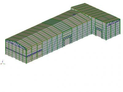
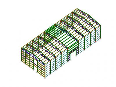
Projecting design calculation carried hangar area 696.14 m 2 consisting of two parts and administrative warehouses, with gable and pent roof respectively.
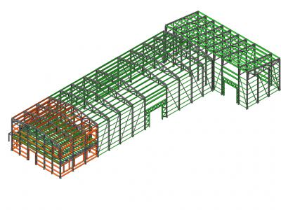
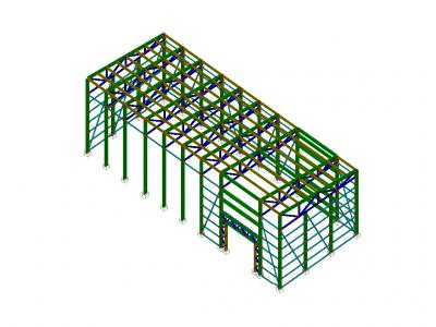
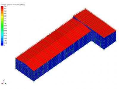
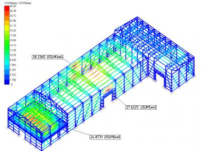
Total estimated construction scheme of the hangar, made in the module APM Structure3D, which is part of the automated calculation and design of structures for industrial and civil construction APM Civil Engineering 11.
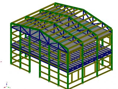
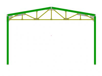
Supporting structure warehouse hangar LSTC made of various sections. Columns, roof truss and floor slabs are made from double C-shaped profile. Runs made of C-shaped profiles of various sections. The metal frame profiles nodes interconnected shaped elements in high-galvanized bolts. Metalwork warehouse hangar attached to the previously constructed foundation by means of anchor bolts.
The load on the metal structure of the warehouse-hangar
Strength calculation and the calculation of the stability of the carrier on the main karkasaprovodilsya (optional) combination of loads, consisting of a permanent, long and short-term loads. Main load combination consisted of a dead weight, payloads, snow loads. The additional load combinations consisted of the forces within the main mix, with the addition of loads from the wind.
Floor loading of the second floor of the office building taken in accordance with paragraph 2 of table 8.3, SP 20.13330.2011.Dlya administrative office space, engineering and scientific staff of organizations and institutions uniformly distributed roof load is 2 kPa.
Snow load (IIIsnegovoy area) were applied according 20.13330.2011 SP.
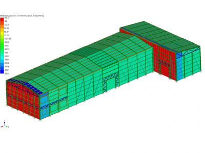
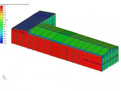
Wind loads (IIvetrovomu area) is applied in two directions: "Wind -X" and "Wind U".
The results of structure analysis
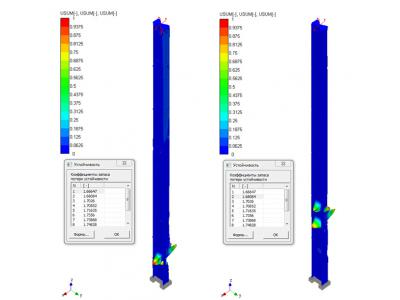
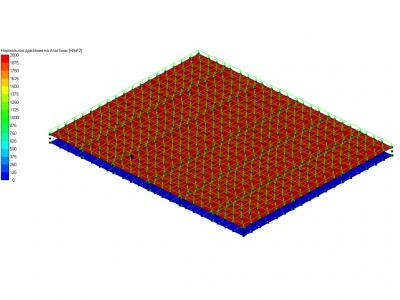
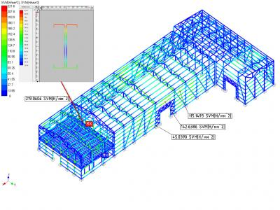
Analysis of the results of static analysis shows that under the given design loads, equivalent stresses arising in the frame structure by using said cell sections, do not exceed the yield strength of the materials used (calculated resistance).
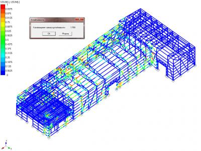
The design does not require additional measures to increase its stability. The minimum safety factor of this design warehouse hangar is 1.77 .
conclusions
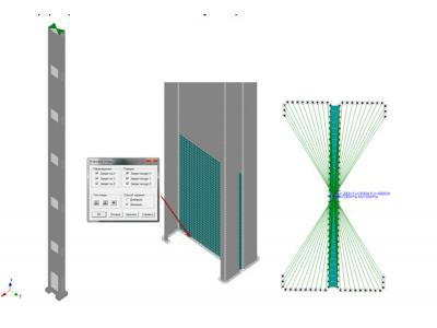
Static analysis performed on the basic design load combination, the stability calculation, calculation of the bearing capacity of the most loaded elements as well as the calculation of construction elements bolted connections. All connections construction warehouse hangar produced high-strength bolts with controlled tightening torque. Using module APMJointbylo chosen number of bolts required for each design compounds.
Summarizing the results, we can conclude that the design of the warehouse-hangar is capable of carrying the load applied to it, corresponding to the construction area, and does not require additional measures to increase the strength characteristics.