R2D2 - 2D frame
ANALYSIS OF 2D BAR BARRIERS
What is the R2D2-Rama 2D program
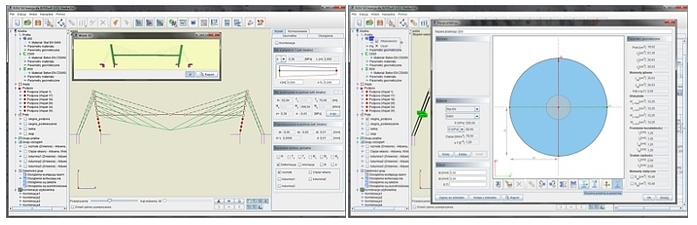
The R2D2-Rama 2D program is a variation of the R3D3-Rama 3D version that has most of its features but is used to perform static calculations of flat bar systems . Thanks to the convenient and transparent user interface, the program can be used not only in design, but also for educational purposes.Entering data in the program is intuitive - the geometry of the system can be defined using only the mouse. Basic construction generators are available. The program includes a library of rolled and cold-bent steel sections, reinforced concrete and wooden elements. Drawing a fairly complicated system is a matter of minutes, calculations and data presentation are carried out in real time (for small systems - up to one hundred rods). The program enables easy introduction of flat bar systems, small systems composed of several bars, as well as large 2D structures containing hundreds of bars and nodes. Thanks to this it is possible to count such construction systems as e.g. multi-storey and multi-nave frames, flat trusses, etc.
Features and capabilities of R2D2-2D frames:
- Static calculations of flat bar systems with constant bar cross-section length.
- The possibility of fully graphical setting and modification of data on the 2D plane of the screen.
- Drawing aids: snap to grid, snap to nodes and landmarks (near, center, intersections, perpendicular) with tracking elements.
- The ability to precisely determine relative coordinates from the keyboard in Cartesian and polar systems.
- Zooming and moving the system and its rotation in real time.
- Possibility to draw rod systems with polylines with rigid or articulated nodes.
- Advanced tracking mode when introducing new elements to the layout.
- Possibility to use snapping to existing nodes, bar midpoints, proxies on bars, bar intersection points and defined mesh points.
- The graphic screen can be locked at any setting of the edited layout.
- Group possibilities of modification of nodes, supports, members and loads.
- Tools for editing entered data, such as: copying, multiple copying in the direction of a given vector (with or without pulling), offsetting, moving, removing bars and nodes, mirroring, leveling nodes, undoing and restoring introduced changes.
- Possibility to stiffen any groups of bars in the node as well as bars and supports.
- Grouping of bars and easy selection of bar groups.
- It is possible to divide the bar with knots into parts while maintaining loads.
- Possibility of merging collinear bars while maintaining loads.
- Member profile manager with a defined library of steel, reinforced concrete, wooden profiles and the ability to extend the library with own profiles and profile assemblies in a given project.
- The possibility of creating cross-sections of bars of any shape, cutting single sections, copying, rotating, moving components of the composite cross-section.
- Automatic calculation of all possible cross-sectional characteristics in the system of local and main axes, including determination of the cross-section core.
- Determination of static moments of any cut-off sections in the main axis system.
- Free definition of bar material. Available library containing: steel, solid and glued wood, aluminum, concrete.
- Possibility of creating hybrid systems due to the material.
- Loads: concentrated forces, concentrated moments, continuous loads, bar heating, temperature difference, settlement of supports, rotation of support.
- Loads given in groups of permanent and variable loads (single or multi) with the possibility of determining load factors.
- The ability to set individual load groups as active or inactive (not included in the calculation), visible or invisible.
- Ability to specify interrelationships between load groups used when building envelopes with automatic validation.
- Possibility of additional custom user combinations.
- Possibility to select bar groups, dimensional elements and load groups directly from the level of the project tree.
- Editable layout elements from the project tree.
- Possibilities of adding elements in the new "ortho" mode on the "xz" plane.
- Possibility to enable 2D preview, cross section of the introduced bar.
- Automatic taking into account the own weight.
- A full set of support types with the possibility of determining their elasticity.
- Parametric generators of spatial rectangular frames, arches (parabolic and circular) and flat trusses.
- The ability to define tie rods and perform static calculations for systems containing tie rods for individual load groups and defined combinations - available from November 2009 .
- Possibility of defining in the system of bars on the eccentric (one-sided or two-sided) with a parallel axis of the bar - the function is available from November 2009 .
- Results for individual load groups, any combination of load groups and a defined combination, as well as the envelope calculated automatically by the program.
- Determining the true envelope of normal stress and calculating normal stress for individual groups and the sum of load groups, combinations and envelopes.
- The possibility of visualization of a static diagram building the indicated envelope extreme.
- Determination of the diagram of normal, tangential and reduced stresses at any point on the bar cross section.
- Finding the place where the maximum reduced stress occurs.
- Quick preview of the structure in 3D view, allowing selection of bars with exceeded allowable normal stresses.
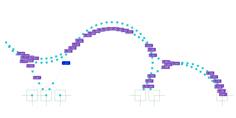
- The ability to visualize the results of internal forces, reactions, deformations and normal stresses on the monitor screen (for the entire system and a single bar).
- The ability to hide parts of the project structure at the stage of data editing and viewing the results.
- Visualization of system deformations - real-time animation.
- Creating many different reports containing tabular and graphic results in RTF format.
- Possibility to freely set the scope of the report and its form (fonts, frames, etc.).
- Concise form of reports.
- Wide possibilities of interface modification, program and project settings as well as data and results presentation.
- Adaptation of static calculations to the needs of dimensioning of steel and wooden structures.
- Bilateral cooperation with InterStal and InterDrewno dimensioning modules .
- Possibility of automatic dimensioning of the overall system as a whole, based on dimensioning types assigned to bar groups and defined dimensional elements ( in InterStal and InterDrewno dimensioning modules ).