UM DRIVE LINE
UM Driveline
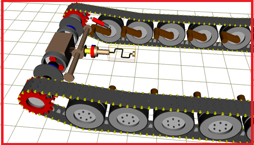
Program package Universal Mechanism includes a specialized module UM Driveline, which contains force elements for simulation of drivelines e.g. in road, tracked, rail vehicles and other mechanical systems.
Mechanical rotation converter with a constant ratio
The element is used for simplified modeling a mechanical rotation converter with given transmission ratio i12 .In particular, the force element models gear trains, e.g. a gearbox.
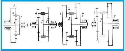
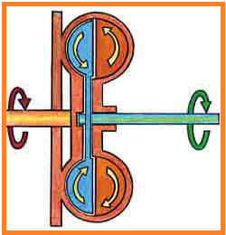
Simplified model of a planetary drive
The force element is used for simplified modeling planetary gearing of four types shown in the figure. Simplification consists in neglecting the inertia properties of planet gears, i.e. it is assumed that kinetic energy of planets is small compared to energy of other parts and shafts. The model takes into account the compliance of teeth and bearings by introduction of an equivalent stiffness constant.
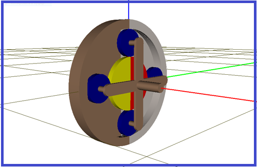
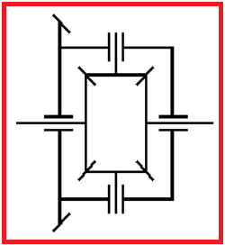
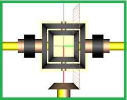
Differential
The differential is modeled as a force element connecting the input and axle shafts. The mathematical model of the differential is simplified by neglecting the inertia properties of the crown wheel, crown wheel housing and pinion gears, i.e. it is assumed that their contribution in kinetic energy is small. The model takes into account the compliance of side gears and pinion teeth as well as pinion bearings by introduction of an equivalent stiffness constant.
Fluid coupling
UM model of a fluid coupling is described by dependence of the torque coefficient on the transmission ratio.
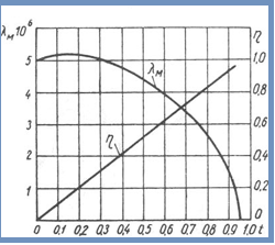
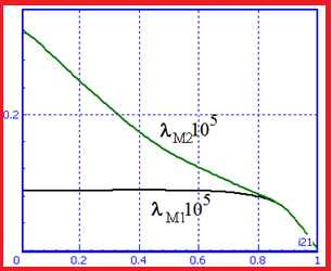
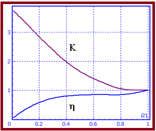
Hydraulic torque converter
The torque converter model can be described in several ways. Here are the equivalent converter description variants (the dependences of characteristics on the transmission ratio).
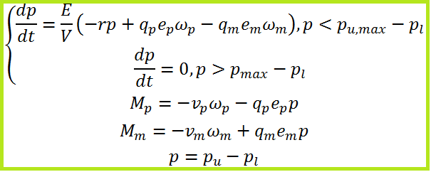
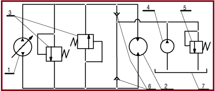
The following mathematical model of the hydrostatic drive is implemented:
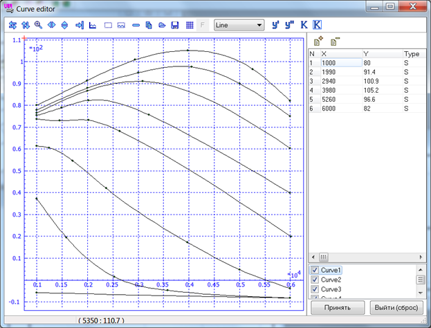
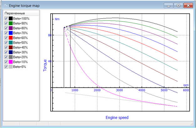
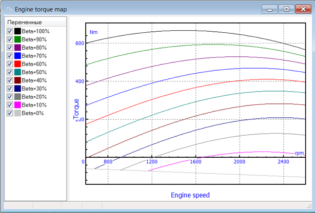
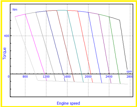
Internal combustion engine
The UM model of internal combustion engine (ICE) is a torque Me нapplied to the engine crankshaft. The value of the torque depends on the shaft speed ne∈ [nmin,nmax] , position of the throttle β ∈ [0,100%].
Me = Me(ne,β)