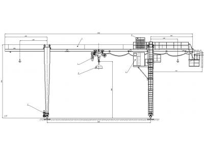
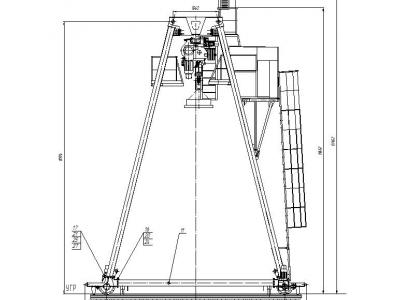
Under the agreement with JSC "Tulazheldormash" specialists of STC APM executed strength calculation of steel gantry crane KK10 using complex APM Structure3D, which is part of APM WinMachine system, version 10.1. In accordance with the wishes of the customer analyzed tensely deformed state of the contact carrier beam section trolley arising during the motion. Initial data for construction of computational models of the bridge is transferred to the customer assembly drawings and assembly three-dimensional solid models.
In the process of creating the model the following normative documents were used:
1. SNIP 2.01.07-85 *: Loads and effects.
2. GOST 27584-88 *: Bridge and gantry electric cranes. General specifications.
3. GOST 25546-82: Cranes. Modes of operation.
3. SNIP II-23-81 *: Steel structures.
Strength calculation of steel structures of the crane bridge
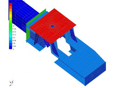
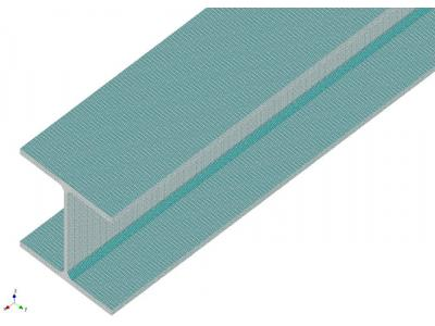
The models of individual parts of the gantry crane, which are then gathered into a single model. As a finite element model to create as separate parts and the entire pattern as a whole, used plate (shell) finite elements. Final calculation model design gantry crane and its fragments showing the internal structure shown below.

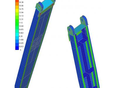
Application of loads carried out in phases, by establishing loadings, each responsible for a particular power factor.
The calculation was made taking into account the dead weight and payload (load is applied to the bottom shelf of the I-beam in the four zones, modeling trolley rollers). To calculate all possible variants the effect of external factors on the design created 4 combinations loading.
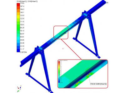
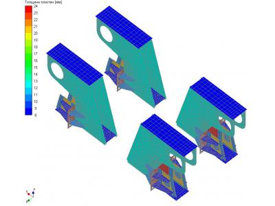
In calculating the identified maximum equivalent strain and corresponding displacement for load combinations; calculation results are shown below.
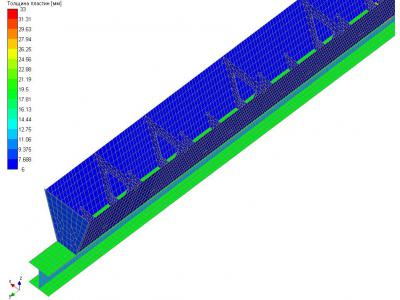
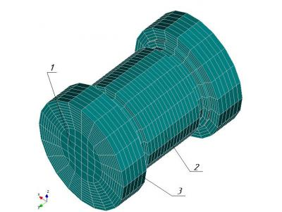
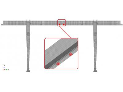
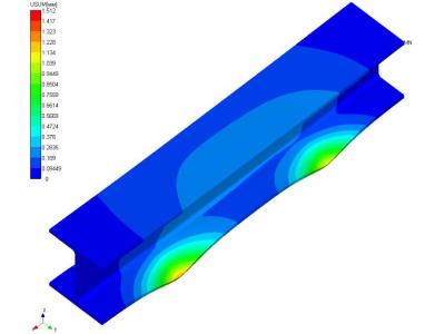
Strength calculation of the lower flange I-beam
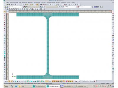
To calculate the lower flange proximate the bridge girder (I-section 35K2 SRT ACHSM 20-93) built solid model portion of the beam length 2m. This model was intended only for the analysis of the local stress-strain state occurs when moving the trolley along the bridge gantry crane.
In this model, the extreme ends of the beam clamped, ie prohibits all displacements and rotations around all axes, that according to the Saint-Venant no significant effect on the picture of the stress-strain state in a local portion of the structure remote from the supports.
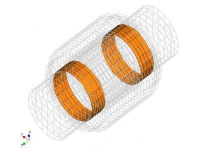
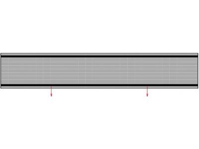
The load on the trolley attached to the bottom flange beams on the roadway platforms 4 mm 4h73 size (along and across the beam respectively). In this case, the size of the site of application of forces corresponding to the dimensions of the contact area that occurs when moving trolley.
the following conclusions were drawn from the results of the calculations:
1. Analysis of the results of static analysis shows that for given loads calculated equivalent stresses arising in the structure of the gantry crane elements do not exceed the yield strength of the materials used, i.e. necessary strength is provided. In the worst case load (combination №2 loadings) the safety factor for the yield strength is not much greater than unity and is equal to 1.06.
2. In order to increase the safety margin is recommended to make the arm elements and the lugs of steel 09G2S grade (strength class 325), which will increase the safety factor to a value of 1.3.
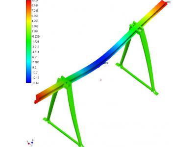
3. The maximum deflection of the structure of the gantry crane, arising from external loads do not exceed the allowable limit. That is a necessary rigidity is provided by the supporting frame.
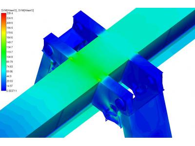
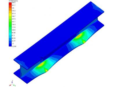
4. Check the bearing capacity of the most loaded cell structure (bottom shelf bridge beams) on the solid model showed that the stresses arising in the zones trolley roller contact, do not exceed 268.5 MPa, and a local trough shelves no more than 1.512 mm. Safety factor for the yield point in this case (the beam material - Steel 09G2S) is equal to 1.21. Thus, the bearing capacity of the structural member is provided.
5. The level of stress to a considerable part of the bridge structure is very low. This means that there is considerable scope for improving the design and the reduction of its metal content.
Summarizing these results, we can conclude that the gantry crane design is capable of carrying loads applied to it corresponding to technical requirements, and does not require additional measures (except as indicated) to increase the strength characteristics.
This work has shown the applicability of structural analysis module APM Structure3D to solve complex problems of structural analysis of materials handling equipment.


