Crane, Vologda
With APM StructFEM Prof. software package, which is part of APM WinMachine system, version 9.5, the specialists of STC executed APM strength calculation of steel bridge crane.Bridge crane actually consists of two independent parts - the bridge and trolley. Strength calculation of these parts is produced independently, and the results of calculation of the reactions in the supports trolley were the original data for calculating the metal bridge. Initial data for construction of computational models of the trolley and the bridge is transferred to the customer assembly drawings and assembly three-dimensional solid models.
Strength calculation of the trolley of the bridge crane.
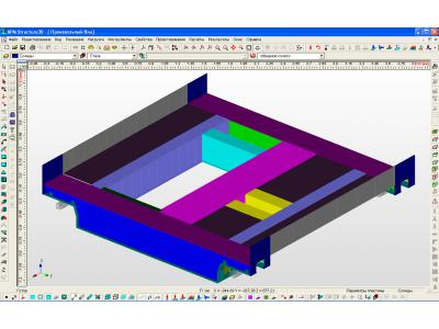
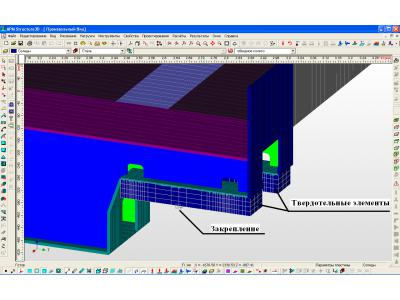
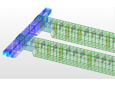
Direct use of transmitted customer solid model for subsequent calculation was not possible. Since almost all the structural elements are made of sheet metal, to obtain reliable results, it was necessary to choose a very small step decomposition. The calculation of this model with the help of an ordinary personal computer can cause great difficulties. In this connection, all the design elements were modeled plate finite elements, thereby reducing the dimension of the problem with a few million to 34,000 finite elements. Finite element model trolley executed in module APM Structure3D, in the images represented below.
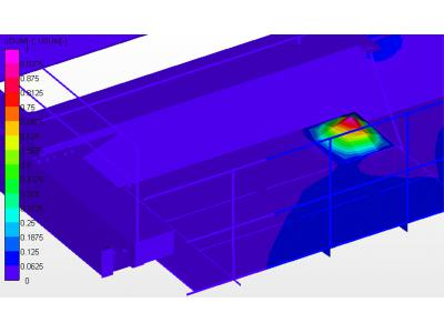
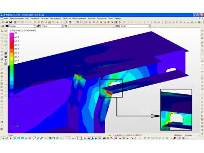
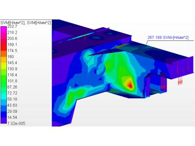
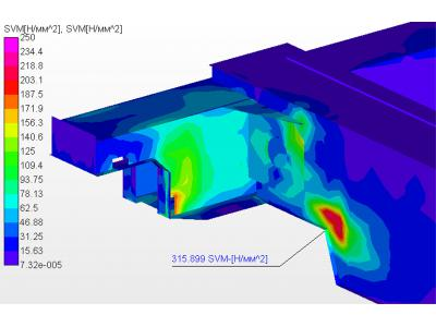
As a result of the static analysis obtained map equivalent (von Mises) stress load carriage.
Analysis card total linear displacement elements of a structure model with respect to the unloaded state shows that, firstly, the maximum displacement is less than the norm, and, secondly, it makes an element not of interest from the viewpoint of carrier trolley ability.
This analysis led to the following conclusions:
1. The static strength of the beam at the roller trolley is not provided, so the need to strengthen the contact area of the roller bearing housings beam with choices or other circuit mounting the bearing assemblies to the frame of the trolley.
2. It is possible to reduce the thickness of sheet metal used in the manufacture of beams, without prejudice to the bogie structure bearing capacity.
3. The nature and magnitude of the strain (maximum 2.2 mm) revealed that in operation the trolley is not significant frame skewing and jamming of the frame is completely eliminated on the rails.
4. For a given design load will not lose stability.
Strength calculation of steel structures of the crane bridge.
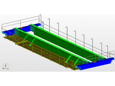
Specialists of STC APM established a model of individual parts of the bridge crane, which are then assembled into a single model. As a standard finite element in creating both individual parts and the whole bridge model entirely, used rod and plate (shell) finite elements. Final calculation model of bridge crane bridge structure is shown in the image below.
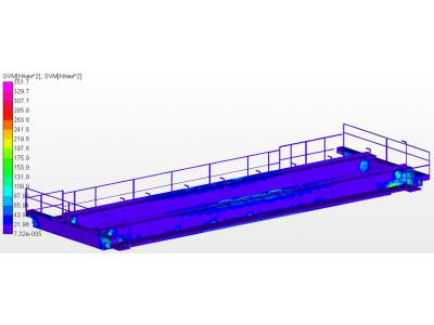
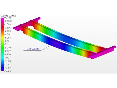
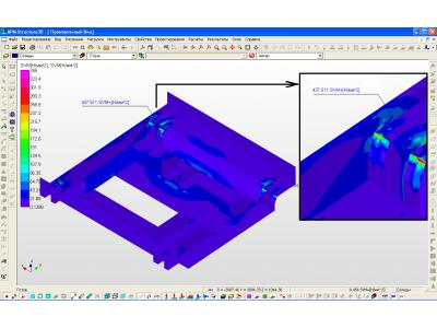
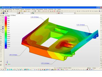
One of the results of a static analysis is a map equivalent stress (von Mises) crane bridge when the trolley in the middle of the transit of the beam
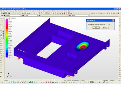
After the static analysis of stability calculation of construction of the bridge crane model was conducted. buckling form to determine the least stable construction element. In this case, the elements are the least stable working platform deck plate bridge, are unaffected by the main load.
The following conclusions can be drawn based on the results of the calculations:
1. The highest stresses occur in the beams span, wherein in the case when the trolley is in the middle position. Therefore span beam construction in these areas requires strengthening.
2. The stress level of the structure to a large span and bridge end beams is very low. This means that there is considerable scope for improving the design and the reduction of its metal content.
3. The margin of stability is sufficient. The least stable element design are the work platform deck plate on which no main load.
This work has shown the applicability of structural analysis module APM Structure3D to solve complex problems of structural analysis of materials handling equipment.