The beam of the prestressed concrete
object model
Carried out a verification calculation and examination of the floor beams prestressed concrete.
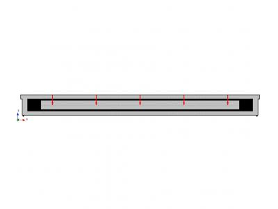
Type of study reinforced concrete beam: SBE18-2V2 (Option 2). Armature d = 18 mm, the material - the steel grade AV (prestress value σ 0 = 650 MPa). The geometrical dimensions of the beam: 950 mm length 17, width 300 mm, height 1490 mm. Total estimated model beam, made in the module APM Structure3D, is shown below.
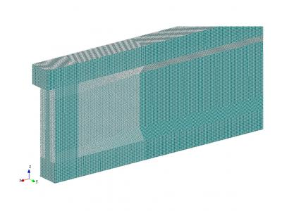
onsidered beam is pivotally supported on a building column. Span 17 600 mm.
Load, impact and combinations thereof
load values were set in accordance with the requirements
1. SP 20.13330.2011 Loads and effects.
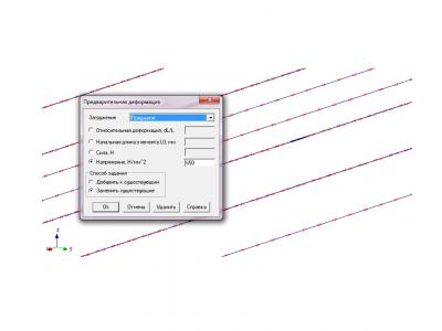
Uploading models performed several load types: constant (own weight of the structure, prestressing reinforcement) and time (the load of the weight of the equipment, the people, the stored materials and products, and snow load).
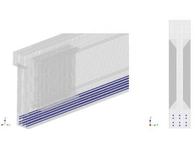
The calculated beam provides the use of a pre-stressed reinforcement. As used tendon and thermomechanically hot rolled hardened steel AV (A800) class. The magnitude of the prestress is 650 MPa.
After all the stress on individual loadings were created linear combinations of loads to which each of the loadings entered with the corresponding coefficients.
Verification load
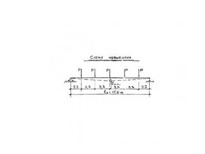
To assess the quality of the constructed model, as well as its operation, beams verification calculation was performed at the specified test load in IL rafters 26-79 SB3-18-1V2, SB3-18-2V2. Load application circuit is shown below. The amount of force F = 13.4 m.
Analysis verification calculation
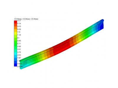
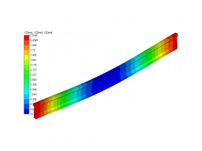
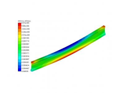
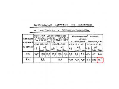
According sheet 4 IL rafters 26-79 SB3-18-1V2, SB3-18-2V2 controlling the vertical deflection of the beam under consideration when tested for toughness and crack resistance, of the corresponding load is 5.7 mm.
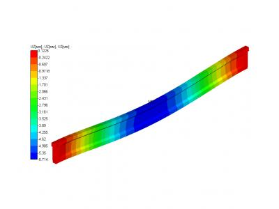
The results of static analysis are in good agreement with the experimental data given. Maximum deflection pattern at said load, in the center of the span is 5.714 mm.
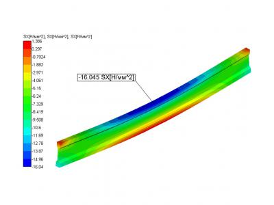
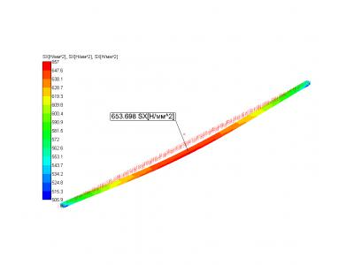
The calculation results