APM Studio 14V
APM Studio – 3D objects pre-and-post processor for finite element analysis
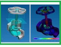
APM Studio is pre-and-post processor for finite element analysis of surface and solid models with STEP file support. It is one of the APM WinMachine basic tools. The module includes built-in finite element mesh generators with different options. It performs static, buckling, modal and heat analysis of parts and assemblies.
Module purpose
- Create or import a model for analysis.
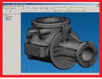
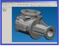
- Automatic generation of the finite element mesh and manual mesh modification with automatic definition of contact surfaces.
- Different types of FE analysis.
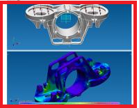
- Results viewing.
Analysis in APM Studio
APM Studio uses APM Structure3D computational kernel and can perform analysis of following types:
- Static.
- Buckling.
- Modal (including pre-tensioned systems).
- Nonlinear.
- Stationary heat.
- Fatigue.
Loads
Different loads types are available in APM Studio.
- Pressure
- Surface and edge distributed force
- Translational and rotational acceleration
- Hydrostatic load
- Bearing contact load
- Load by user specified law
- Temperature
- Volume distributed load
Contact type
- Rigid.
- Sliding.
- User defined
Modeling in APM Studio
Operation in APM Studio finally results in surface and solid objects, created by means of 3D modeling function.
One of the basic solid modeling objects is a sketch. The sketch can be one of orthogonal coordinate planes or an arbitrary plane in space. All 2D drawings are fulfilled as a sketch. In this case the following functions are used: drawing of lines, circles, arcs, polygons, setting fillets and bevels, truncation, aligning along the border, displacement, copying, moving, mirroring, creating arrays — rectangular and circular, rotation of objects etc.

Data can be transferred into the sketch from external graphics editors, by means of its import from *.dxf, *.agr file formats. Export of geometry from the sketch to 2D APM Graph editor is also possible. 3D models are imported to APM Studio via the exchange STEP format. Further you can change its and prepare for assessment of the stress-strained state.
Surface modeling
Surfaces are created by means of operations on 2D curves, prepared in sketches. APM Studio makes it possible to form surfaces by following instructions: sphere, extrusion along the normal and arbitrary curve, rotation, contour plane etc. Curved surfaces can be defined by a set of arbitrary cross-sections.
To create more complex surfaces, the following operations with finished surfaces can be used: intersection, fillet, setting bevels, sewing of surfaces, removing existing edges.
Solid modeling
Solid bodies are created by means of extrusion, rotation, torsion etc. carried out on 2D objects prepared in sketches. To create complex models it is necessary to select a one of the following operation: unification, subtraction or intersection. Therefore, the model on the screen will be a result of the selected operation’s type on the existing and newly created object.
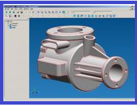
APM Studio interface
The front-end interface of APM Studio can be divided into five regions: a main menu, a working window, a toolbox, an operations tree window and a status line. These areas can be arranged by the user on the screen to his discretion.
Operations tree
All objects created by the user in APM Studio are reflected in the operations tree. The root of the operations tree is a Part. The first element of the operations tree is the Geometry node. It contains the coordinate planes, which can be chosen as the sketch planes. Further the objects are following: sketches, curves, surfaces, solid bodies. Every surface or a solid body drawn in APM Studio is designated with a node in the operations tree. When in the choice mode, required elements can be chosen from the operations tree and the following operations with them can be performed: deletion, modification etc.
Viewport
The viewport is a main window for modification and viewing operations, performed in APM Studio. A global orthogonal coordinate system is introduced for orientation of objects in space.
The viewport has two modes- the sketch editing mode and the surface editing mode, as well as of solid bodies.
Shortcuts
When working with APM Studio several operations are called most often and sometimes it is not convenient to access them via menu or toolbar. Editing environment of APM Studio contains speed buttons, called by means of the mouse and keyboard keys, which are necessary to move and rotate view as well as for dynamic zooming.
When creating some curve it is possible to call an object snapping which is necessary for this specific matter. It is called a local snap.
The system of context menu is developed rather widely for different cases of objects editing.


