Heat exchanger cooling power storage pool
with VVER-1000 strength calculation to estimate the residual life
In calculating the evaluation circuit is a heat exchanger strength dampening unit of storage pools. Heat exchanger is calculated taking into account the strength of extension to 30 years of life, inclusive. Analysis strength heat exchanger is conducted according to PNAEG-7-002-86.
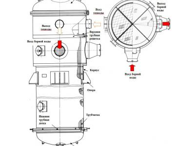
Description of the construction
Exchanger dampening basejna shutter circuit for cooling distillate loop service water storage pool.
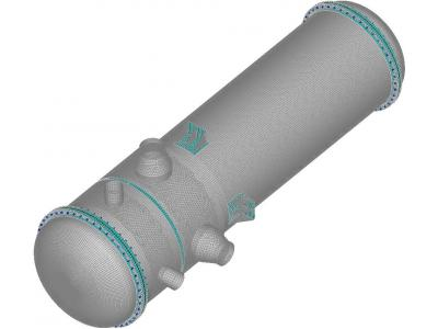
The heat exchanger is a vertical, single-hull, zhestkotrubny apparatus shell and tube type, four-in tube and the space between the tubes countercurrent to the movement of media.
"Hot" distillate moves in the annulus, the process water in the pipes.
Heat exchange surface comprises tubes ø18h1,4 4792 mm, arranged in an equilateral triangle with a pitch of 23 mm, attached to the tube sheets by rolling and obvarkoy. The position in the casing tube fixed spacer grids that are interconnected tube beacon.
The housing of the heat exchanger is made of shells and ø1832 ø2032, welded together using an adapter.
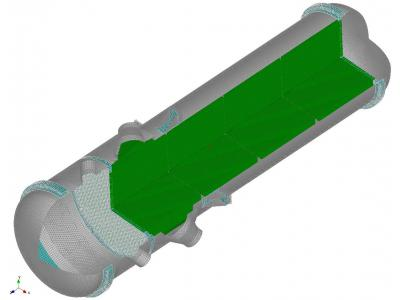
For the organization of the four strokes of the annulus in the housing mounted longitudinal partitions.
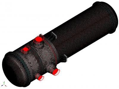
Process water is supplied and discharged ø325h12 nozzles in a cylindrical chamber with an elliptical bottom. The chamber is divided by partitions into three cavities for the organization of the four strokes of the tube space.
In the heat exchanger of the tube and the annular space provided ø25h2,5 vents and drains and ø57h5,5 ø38h3,5
Initial data
The main design parameters
| Name parts of the vessel | Pressure, MPa | Meaning temperature, ° C | Working environment |
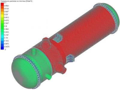
calculated parameters | annular space | 1 | +150 | active distillate |
pipe space | 0.6 | +150 | service water | |
Working condition | annular space | 0.7 | +150 | active distillate |
pipe space | 0.3 | +150 | service water | |
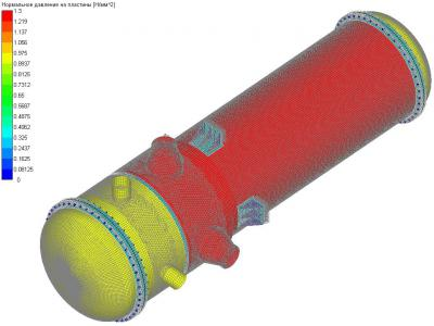
hydraulic tests | annular space | 1.3 | +5 | active distillate |
pipe space | 0.9 | +5 | service water |
The calculated loads on fittings exchanger
Dimensions fittings | Category and size of loads | |||||||
NueM in Nm | Nue (moment magnitude)M p , N · m | NueF in H | Nue (swing power)F p , H | Nue + PPM pz , Nm | Nue + PPF pz , Nm | Nue +MDEM MDE Nm | Nue +MDEF MDE Nm | |
Ø325x12 | 15800 | 33000 | 14600 | 30500 | 19500 | 17900 | 21900 | 20500 |
Ø628x14 | 22800 | 50000 | 19200 | 42100 | 28000 | 23400 | 31500 | 26800 |
Allowable stress, MPa
Material | Nue | GI | ||||
0.5 [ s ] | [ S ] | 1.3 [ s ] | 0.5 [ s ] | [ S ] | 1.3 [ s ] | |
steel 20K | 68.6 | 137.3 | 178.5 | 72 | 144 | 187.2 |
steel 12X18H10T | 62 | 124 | 161.2 | 65.3 | 130.6 | 170 |
According to PNAE G-7-002-86raschot on the strength equipment is carried out in two stages:
- calculation of the choice of the main dimensions;
- span calculation.
As part of the verification calculation for the heat exchanger following calculations were performed:
- calculation of the static strength;
- calculation of the stability;
- calculation on a cyclic durability;
- calculation of the resistance of brittle fracture;
- calculation on seismic effects;
- calculation of the vibration.
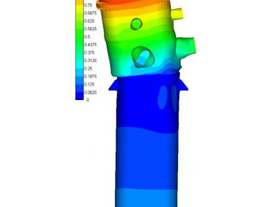
Calculation of the static strength
These groups categories voltage stress ( s ) 1 and ( s ) 2
Nue | ||||
calculated area | ( S ) 1 | Allowable stress [ σ ] | ( S ) 2 | allowable stress 1.3 [ σ ] |
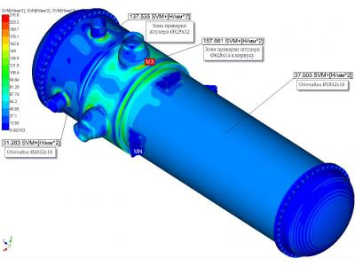
Zone welding nozzle body Ø628x14k | - | - | 158 | 161.2 |
Zone welding nozzle body Ø325x12k | - | - | 138 | 178.5 |
Shroud distillate chamber Ø1832x16 | 37 | 124 | - | - |
Shroud industrial water chamber Ø2032x16 | 31 | 137.3 | - | - |
Flange DN 1800 | - | - | 57 | 161.2 |
Flange DN 2000 | - | - | 55 | 178.5 |
Tube plate DN 1800 | - | - | 12 | 161.2 |
Tube plate DN 2000 | - | - | 26 | 161.2 |
GI mode | ||||
calculated area | ( S ) 1 | Permissible napryazhenie1,35 [ σ ] | ( S ) 2 | allowable stress 1.7 [ σ ] |
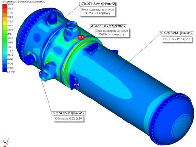
Zone welding nozzle body Ø628x14k | - | - | 214 | 222 |
Zone welding nozzle body Ø325x12k | - | - | 170 | 245 |
Shroud distillate chamber Ø1832x16 | 70 | 176 | - | - |
Shroud industrial water chamber Ø2032x16 | 62 | 194 | - | - |
Flange DN 1800 | - | - | 69 | 222 |
Flange DN 2000 | - | - | 77 | 245 |
Tube plate DN 1800 | - | - | 28 | 222 |
Tube plate DN 2000 | - | - | 55 | 222 |
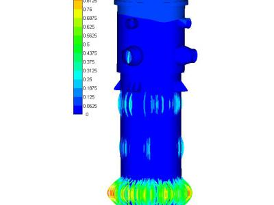
Calculation for cyclic durability
When operating the heat exchanger apparatmozhet the following states:
- initial (unloaded) state - №1;
- mouthfuls - №2;
- working condition - №3.
- loading of the hydraulic pressure test - №4;
In order to justify the fatigue strength of the heat exchanger for 30 years accept:
- the number of hydraulic testing N = 5;
- the number of outputs in the operating state of N = 200.
loading units for the calculation of the fatigue strength of the heat exchanger are as follows:
- block 1: 1-2-3-2-1 N = 200;
- block 2: 1-2-4-2-1 N = 5.
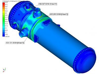
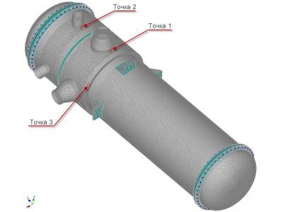
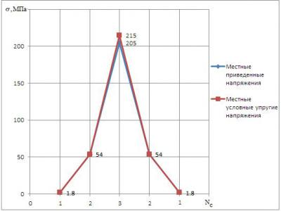
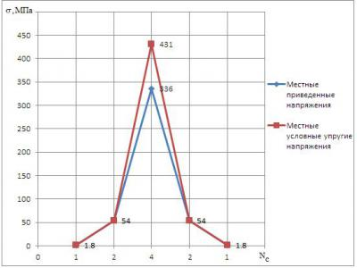
Determination of accumulated fatigue damage at point 1
room block | σ max , MPa | Np | σ min , MPa | Np | σ a , MPa | N | [N] | a |
1 | 215 | 3 | 1.8 | 1 | 107 | 200 | 6 ∙ 10 4 | 33 ∙ 10 -4 |
2 | 336 | 4 | 1.8 | 1 | 167 | 5 | 3 ∙ 10 4 | 1,7 ∙ 10 -4 |
|
|
|
|
|
|
| Σa | 34,7 ∙ 10 - 4 |
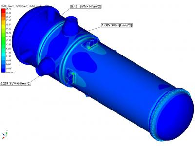
Determination of accumulated fatigue damage at point 2
room block | σ max , MPa | Np | σ min , MPa | Np | σ a , MPa | N | [N] | A |
1 | 184 | 3 | 0.48 | 1 | 92 | 200 | 7 ∙ 10 4 | 28,5 ∙ 10 - 4 |
2 | 240 | 4 | 0.48 | 1 | 120 | 5 | 5 ∙ 10 4 | 10 - 4 |
|
|
|
|
|
|
| Σa | 29,5 ∙ 10 - 4 |
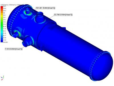
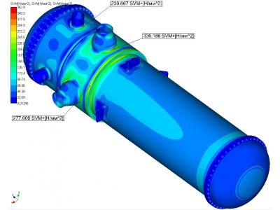
Determination of accumulated fatigue damage at point 3
room block | σ max , MPa | Np | σ min , MPa | Np | σ a , MPa | N | [N] | A |
1 | 131 | 3 | 5.28 | 1 | 63 | 200 | 10 6 | ∙ 10 2 - 4 |
2 | 278 | 4 | 5.28 | 1 | 136 | 5 | 4,5 ∙ 10 4 | 1 ∙ 10 - 4 |
|
|
|
|
|
|
| Σa | 3 ∙ 10 -4 |
The maximum accumulation of fatigue damage in a heat exchanger at the point 1 and in view of the increased service life of 30 years is:
and = 34,7 ∙ 10 -4 <[ a ] = 1.
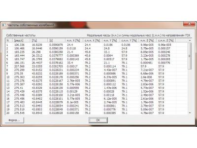
Calculation of seismic effects
Viewed relates to a heat exchange apparatus Ikategorii earthquake resistance of NP-031-01, however, in accordance with PNAEG-7-002-86 it must be based on a combination of load and Nue + PP + MDE Nue. Seismic loads were determined using the generalized spectra MDE response level to mark 0.0 m (Annex B) at the lower natural frequency of 16.92 Hz exchanger.
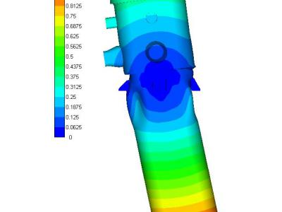
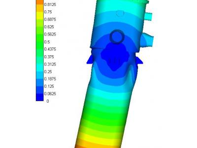
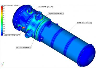
These groups categories voltage stress ( s ) 1 and ( s ) 2 for state Nue + MDE
calculated area | ( S ) 1 | Permissible napryazhenie1,4 [ σ ] | ( S ) 2 | Permissible napryazhenie1,8 [ σ ] |
Zone welding nozzle body Ø628x14k | - | - | 210 | 223 |
Zone welding nozzle body Ø325x12k | - | - | 230 | 247 |
Shroud distillate chamber Ø1832x16 | 35.5 | 174 | - | - |
Shroud industrial water chamber Ø2032x16 | 35.9 | 192 | - | - |
Flange DN 1800 | - | - | 57.95 | 223 |
Flange DN 2000 | - | - | 54.7 | 247 |
Adapter | - | - | 55.3 | 223 |


