Strength calculation of the building department store on the main load combination
The company OOO "ChernomorStroyProekt" engaged in the design of residential high-rise buildings on the Black Sea coast from Anapa to Sochi with the passage of state examination of the project. And also working on designing the reconstruction and carries out construction and technical expertise.
In September 2007, employees of the company STC APM completed the verification calculation of bearing reinforced concrete frame and steel roof department store on the ground and a special combination of loads. Location of the store - the city of Tuapse
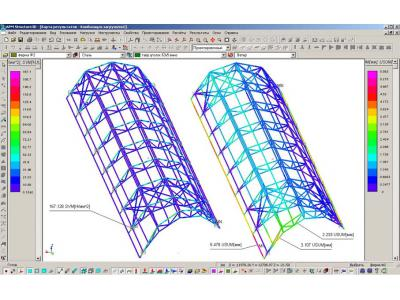
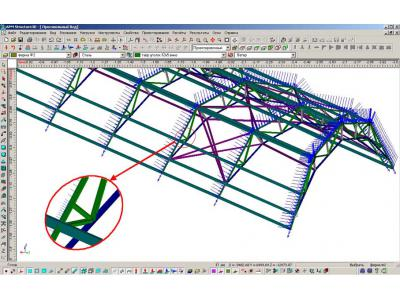
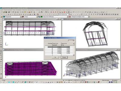
First it was modeled and is counted separately from the metal structure of the roof of the building. It was shown that the roof frame is able to carry the applied loads, but some beams have insufficient safety factor for the yield strength of the material. in the floor structure of farms added an additional pin - In connection with this modification was proposed. It is possible to raise the rigidity of the frame and increase the safety factor of yield strength for the upper chord beam of nearly 30%.
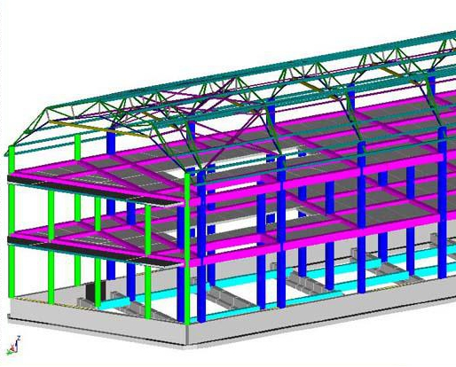
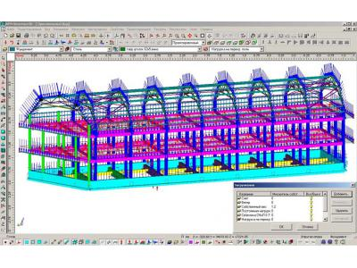
Further, according to the drawings provided by the customer it was built concrete frame and the model assembled into a coherent whole. For ease of loading of the building model in the APM Structure3D module function is used to work with downloaded. This allows you to have easy access to a visual display of power and the possibility of editing and doing a calculation DCS possible.
The list of applied loads included: own weight with the corresponding coefficient of reliability for the load, the useful load on the floors, the load of the weight of the interior walls, the load on the girders of the weight of the outer walls, the load on the internal escalators, the load on the staircases, in mechanical facade load the load of the deck on the roof, wind and snow load and seismic load (seismicity of the construction site on the map a - 8 points). To account for the seismic action in parallel computed natural frequencies and their own forms of construction.
As a result of the verification calculation of RC frame it was necessary to assess the correctness of selected cross-sections of concrete elements and the adequacy of the proposed reinforcement. The calculation is performed on the first and second groups of limit states. The main evaluation index in this case are: the use of the coefficients and evaluation of valves width non positive cracking.
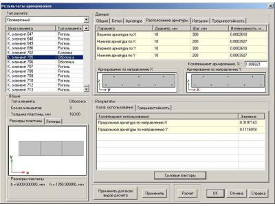
The data obtained from the coefficients using reinforcement (less one), and estimating the width nonpositive cracking (maximum design width - smaller than the permissible values) led to the conclusion the design ability to perceive the appended force factors
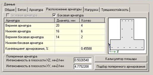
Also, special attention was paid to the assessment of efficiency of the foundation, which in this design is a T-section beams set on an elastic foundation.
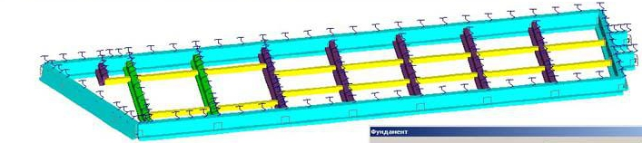
Composition soil under the foundations - pebble with loamy soil, clay rarely semisolid to tugoplastichnogo with filler to 29.5% with lenses gravel ground. The layer thickness varies between 5.5 -. 6.5 m Specific adhesion CII = 9 kPa, the internal friction angle φII = 27˚, soil density rII = 2.0 g / cm3, J = 0.25. (Customer data).
According to the first and second groups of limiting states passed by foundation beams (complex index - maximum valve operating ratio less than unity, the maximum value of a short crack opening width is 0.19 mm (bases under an escalator) that is less than 0.4 mm - maximum allowable widths cracking conditions of safety valves).
Maximum precipitate foundation was approximately 10 mm with a thickness of 5 m punching. Maximum draft is less than the ultimate strain of the base 10 cm (Table E.1 SP 50-101-2004 Design and apparatus of the foundations of buildings and structures).
Thus, a comprehensive analysis of the job shop design shown its efficiency in given design conditions.


