APM WINMACHINE FEATURES
TRANSMISSION - APM Trans - APM DRIVE - APM Cam - Apm Screw
APM Trans
APM Trans - The mechanical transmissions are the maintype of transmission mechanisms used to carry energy (movement) from enginesand motors to operating elements of various machines and devices. APM Transperforms designing and calculation, generates working drawings of themechanical transmissions. Main Features - Gearing design - Longevity calculation - Torque calculation Design with limitations Working drawings generation Gearcutting and meshing modelling External customized.
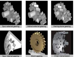
APM Trans let perform complex of mechanical transmission design and technological calculations (both design and checking) as well as automatically create working drawing of designed transmission elements. With APM Trans you can calculate all widely used types of transmissions:
Types of transmissions - External And Internal Spur Gearing - Helical Gearing - Herring-Bone Gearing - Bevel Gearing With Standard Involute Teeth And Circular Teeth - Worm Gearing - Belt Transmissions - Chain Transmissions - Transmission design -
When you make transmission design, you specify the required parameters, such as externalload, materials, thermal treatment, kinematic performances, lifetime, etc. Using these data the APM Trans calculates general dimensions of the transmission based on the criteria of tooth bending strength and pitting resistance. To make gear design the following initial data must be specified output torque-longevity-working conditions, transmission ratio, etc. You can impose limitations on dimensions of the transmission, for example you can design the transmission with the given inter axial distance, etc.
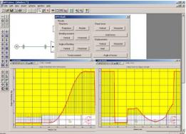
All calculations can be performed both for constant and time variable real loading. Variable load are specified by one of the predefined working conditions and by userdefined one. APM Trans proposesl corresponding graphical tools to set anyworking condition.
Design and cheking calculation are based on criteria - Cylindrical, bevel and worm gearing calculations are based on contact fatigue strength and bending fatigue strength criteria
Chain transmission calculations are based on criterion of chain hinge wear resistant - Belt transmission design is based on belt load capacity and longevity - Design with constraints You can impose limitations on dimensions of the transmission, for example you can design the transmission with the given axial distance, etc.
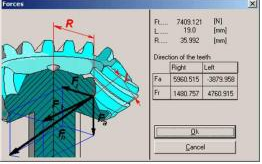
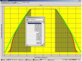
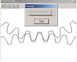
APM Trans results - The complete list of transmission parameters are calculated - Transmission geometry parameters - Forces acting on transmission shafts - Acting stresses and allowable stresses - Gear wheels quality checking - Tooth profile - Working drawing of drive and driven transmission elements. Load capacitycalculation - APM Trans let calculate the load capacity of the given transmission (with the knowndimensions, material, thermal treatment, etc.). You can do it in one of thefollowing ways - determine the maximum load for the given lifetime of the transmission
determine thelifetime for the given maximum load - Gear wheels quality checking
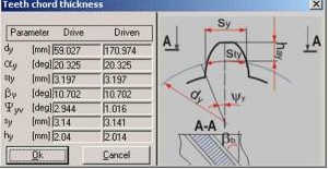
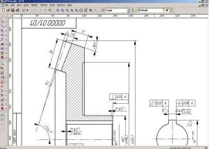
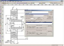
The APM WinTrans performs all test calculations in order to check the quality of gear wheelsmanufacturing, including - Gear face profile parameters checking - Test for the constant chord - Test for the common normal - Test for the chord thickness- Roller test -Test for the different tooth profiles location - Meshing quality test - Working drawings generation - In the APM Trans you can generate the working drawing of the transmission elements you have designed. APM Trans provides you with the convenient dialog tools for makingthese operations. The drawing is saved in the APM Graph file format *.agr. Using APM Graph you can make any additions and corrections to the generated drawing, print it out and save it in DXF file format. When working with drawings in APM Trans you can vary details of transmission construction. set the specifications - fill in the title block of the drawing, etc.
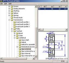
Database - Mechanical database is used to perform strength and geometry calculation of transmission as well as load capacity and wear resistant calculation. Standard dependent data are stored in the database. This data can be customized to satisfy any industry or enterprise standard using APM Base database managment system.
Gear cutting and meshing modeling
Gear cutting modeling is an important part of gear design and is performed by rolling method. This procedure let receive gear tooth profile based on cutting tool and addendum modification.
At the same time it makes possible to control actual size of pinion and wheel teeth. Using APM Trans you can also model teeth meshing that is especially significant for internal gearing where teeth interference is possible.
APM Trans as optimization tool
Using our softwareyou can optimize designed gearing by changing initial data, imposing or removing limitations on some parameters (axial distance, module, bandwidthetc.). In that case APM Trans helps you to consider different variants.
Convenient andeasy-to-use interface
User interface is fairly straight forward and intuitively clear. You need no more than 1—2sessions in order to learn to work with APM Trans.
Download APM Trans Demo
APM DRIVE
APM Drive Engines are used for providing the motion of the executive mechanism. In most cases the driving gear that transforms the initial rotary movement of the engine into a lower-speed output movement is installed between the engine and the executive mechanism. Single- or multi stagedrive units combined with belt and chain transmissions are used as executive mechanism.
APM Drive
Engines are used for providing the motion of the executive mechanism. In most cases the driving gear that transforms the initial rotary movement of the engine into a lower-speed output movement is installed between the engine and the executive mechanism. Single- or multi stage drive units combined with belt and chain transmissions are used as executive mechanism. A gearset, as a rule, contains gearings, shafts and rolling-element bearings which are in case and support the shafts. APM Drive is intended for the comprehensive calculation and generation of the design documentation of all elements of the multi stage reducer including the assembly drawing.
APM Drive let to perform the design of a gear set namely to get gear and worm geometry, to select suitable shaft size and rolling- contact bearing. Based on design calculation it is possible to generate gearset assembly drawing and drawing of separated elements. Besides paletary gears of most used types can be desiged.Calculation of all drive unit elements can be performed both automatically and with manual corrections depending on intermediate results.
Main features - Drive unit design - Design with limitations - Large number of drive elements - Customizeddatabase - Assembly drawing generation - Drawing of drive unit parts generation
The design process of a drive of the rotary movement of the arbitrary structure using APM Drive comes to the determination of kinematic scheme in the special editor, gearset data specifying and the following calculation as well as the result analysis and initial data and results correction. This module works together with themodules of the gear calculation APM Trans, shafts and axes calculation APMShaft, as well as with the module of the rolling- contact bearings calculation APM Bear. The mechanical database APM Mechanical Data is also used in design process and graphic editor APM Graph is used for drawings of the designed elements.
Кinematic scheme editor
Kinematic editor underlies the APM Drive. It is necessary to specify a kinematic scheme of gearset as an initial design step using a special graphic editor. Kinematic scheme specifying means definition of shafts arrangement, gears and bearings mutual positions, gears and bearing type selection. The input and the output of the gear are shown schematically. The number of gearset stages can be arbitrary.
Gears of following types can be used:
gears of all types of the evolving profile (spur, internal spur, helical, herringbone gears), bevel gears with a straight and spiral tooth
worm gears, planetary gears
radial ball bearings
double-lined spherical ball bearings
radial-thrust and thrust-radial ball bearings
thrust ball bearings
radial and needle roller bearings
double-row spherical roller bearings
radial-thrust and thrust-radial roller bearings
thrust roller bearings
Rolling contact bearings of following types can be selected:
Using gears and bearings of above types a gearset of arbitrary scheme can be assembled. APM Drive let define geometrical dimensions of the gears and the shafts, and select suitable rolling contact bearings from the database.
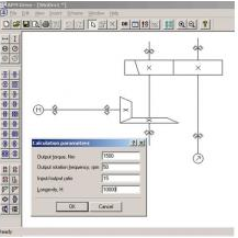
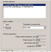
Drive design process begins with its kinematic scheme (see above) and the basic input/output parameters setting. Subdivision of kinematic parameters of gear stages (transmission ratio, moment and number of the turns) can be made either automatically or manually.
Besides the basic gearset parameters
the initial data can be also set - Drive loading mode(constant or variable) - Heat treatment ofthe gears - Shafts material
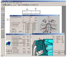
After the pre-calculation you receive gear parameters (such as geometrical dimensions,forces in meshing, cutting and control instrument parameters, etc.; shaft geometry and parameters; types and geometrical dimensions of the rolling contact bearings selected from the database).
Based on pre-calculation results you can specify more exactly the heat treatment of the gear wheels material, and also set some restrictions of their design - module,axial distance, tooth number, helix angle, addendum modification coefficientetc.
The shaft calculation is performed to ensure safety factor for endurance strength 1,5 –1,6. Besides such shaft attributes as chamfers, fillets, keyways, splines and similar are not taken into account in the pre-calculation. They should be entered manually on the appropriate shaft segments, according to chosen gear-shaft connection type. It is required sometimes to specify the shaft diameters for the bearings installation, and also to correct shaft segments, in which the fatigue safety factor has appeared below the required one.
Bearing selection is performed according to its type, shaft segment diameter and required longevity. If APM Drive fails to find automatically the suitable bearing fromthe database, you should change corresponding shaft diameter. All necessary parameters are calculated for each bearing of a gearset. The calculation process in the APM Drive should be restarted after making all required modifications in the drive unit. As a result, the modified drive will be designed taking into account all the modifications.
APM Cam is intended for cam mechanism calculation and design.
APM Cam
Cam mechanism isthe elementary mechanism that is used to transform rotational movement to translation or hobbing motion of pusher. The pusher motion law of cam mechanismis defined by cam geometry and pusher type. Cams are frequently used as controlunit providing required motion low.
APM Cam is intended for cam mechanism calculation and design.
Main Features Cam design
Function law defined by displacement, velocity, acceleration;
Working drawing generation.
The following types of cams mechanisms can be designed
cam mechanism with roller arm - cam mechanism with flat arm;
cam mechanism with roller rocker - cam mechanism with flat rocker.
Initial data
Motion law can be defined as - displacement graph - velocity graph
graph of acceleration by rotation angle of cam.
To design cam mechanism you need to specify cam type, motion law, some geometry parameters of cam and material properties.
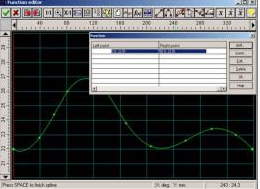
The universal function editor is used to enter motion law function that can consist of several segments represented as linear segments, splines or any their combination. The function law can be defined as analytic function as well.
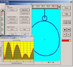
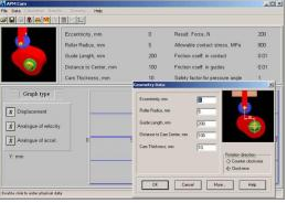
Calculation criteria - Cam profile is calculated based on pusher motion law, diameter — based on pressure angle limitation, and pusher width and radius — based on maximum contact stress.
Calculation results - APM Cam let cancalculate the following characteristics of cam - cam profile both in Cartesian and polar coordinates - angle of pressure - coordinates of theinternal and external envelopings of central profile (for cam with rollers) - animation of cam behavior - create workingdrawing = Working drawing generation
With APM Cam you can generate the working drawings of the cam profile in the APM Graph file format. Further it can be exported in DXF file by user request. APM Cam allows you to change the geometrical parameters of the cam, motion law, and analyze the graph of speed and acceleration. On the basis of this information you can draw a conclusion about correctness of this cam decision.
Apm Screw
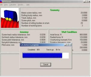
APM Screw is comprehensive software for calculation of screw gears. It allows you to perform a complex analysis of the screw gears, compute its main performances, and select the optimum parameters of gear elements.
APM Screw - Screw gears are used for transformation of rotational movement of the screw to the transactional movement of the nut. They are widely applied in the machine too lindustry, aircraft industry, roboto technics and many other areas of the modern mechanical engineering. Mean while, the existing methods of screw gear calculation collide with number of the serious problems.
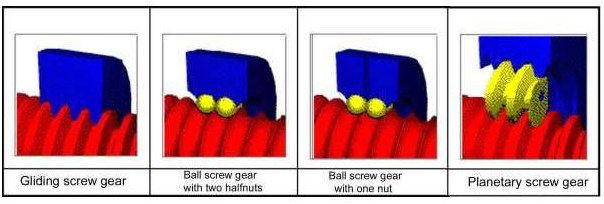
APM Screw is a comprehensive software for calculation of screw gears. It allows you to performa complex analysis of the screw gears, compute its main performances, and select the optimum parameters of gear elements. The most widely used types of the screw gear
In the APM Screw you can calculate the most widely used types of screw gears. For the ball screwgears two sub types can be calculated — with one nut and with two half nuts (thelatter allows the preload use). The theory of the non-ideal contact—the basis of the APM Screw. The main advantage of the APM Screw is that it allows considering the influence of manufacturing errors on the screw gear performances. It becomes possible due to the new theory of non-ideal contact, developed in the Research and Software DevelopmentCenter APM Ltd. This theory is applicable to the wide range of machineelements, such as bearings, screw gears, plain joints, rolling contact guides,etc. It allows you to get reliable values of the contact displacements,stiffness, stresses and all parameters that are depended on the formers, suchas longevity, moment of friction, loss of power, etc.
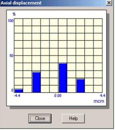
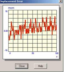
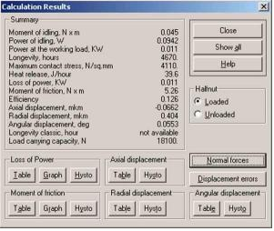
With the APM Screw the following parameters can be calculated:displacements(stiffness) - longevity - moment of friction - maximum contactstress - loss of power - heat release - forces acting onthe rolling bodies - efficiency - positioning errors - Simulation insteadof the single parameter’s calculationDue to the randomly distributed irregularities of the contacting surfaces, the interaction of the screw, nut and rolling bodies has the probabilistic nature and can be adequately described only in the statistical sense. With the APM Screw you get the complete and exhaustive picture of processes that take place when a screw gear works. Virtually Screw allows simulating the behavior of the screw gear at the conditions that you have specified. To provide such opportunity reasonably large series of the parameter values are computed, showing how these parameters are changing. When using these data, you can determine features of the distribution, maximum deviations, fields of dispersion, etc.Displacements and stiffness—the core of the systemStiffness and contact displacements describe how the elements of the mechanical device interact under loading. If you know the stiffness, you can get the reliable values of many other parameters. In the APM Screw the list of 100 nut center positions is computed. Depending on the screw gear type a displacement can have up to three components — xial,radial, angular. When using them it is possible to determine the axial, radial and angular stiffness and compliance with the gear. The list of the nut center positions is the core of the APM Screw.
For each position values of the moment of friction and the loss of power are computed together with the forces acting on the rolling bodies. Stiffness and contact displacements describe how the elements of the mechanical device interact under loading. If you know the stiffness, you can get the reliablevalues of many other parameters.
Friction moment loss of power and forces acting on the rolling bodies are calculated for each considered center position.
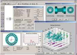
Result representation in different ways - as a table supplemented with the statistical parameters - as a histogram - as a graph - as an animation
When using the appropriate forms of the presentation you get an exhaustive characteristic of the screw gear movement
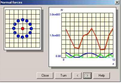
Forces acting onthe rolling bodies
During the rotation of screw gear its rolling bodies (or satellites in the case of the planetary gear) are subject to the normal forces action applied from the screwand nut and depending on the geometry, accuracy, external load, etc.
Existing methods ove ridealize the problem producing over simplified solution. The new approach was developed. It gives a more real picture. In the APM Screw the forces acting on the rolling bodies are computed for the each member of the large series of the nut center positions determined during the gear displacements calculation. As a result you are given a possibility to trace how these forces change in time.
Forces acting on the rolling bodies are presented in two ways::
as an epure - as a graphFriction in the screw gearIn the APM Screw you can determine the following parameters characterizing the action of the frictional forces:moment of frictionloss of powerheat releaseefficiency
For the moment of friction and loss of power a list of 100 values is calculated, so you can determine the features of the distribution of these parameters. The results can be presented either as tables, as histograms or as graphs. The heat release is an integral parameter characterizing the amount of the heat released in the gear due to the friction during a time period of one hour. An arbitrary loading conditions including the preload
Calculations in the APM Screw can be made for any combination of axial and radial forces,over turning the moment and the preload allowed for a screw gear of the given type. External loads by longivity calculation can be considerd to be variable in time. There is a special graph editor for that purpose.