Design for Traverse SAO packaging Kursk NPP
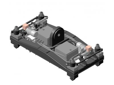
Development of two cross-arms for packaging CAO (type 1 and type 2) was carried out STC "APM" by request of "UfaAtomHimMash" for Kursk plant. Traverse type 1 consists of a frame structure with 4 locking mechanisms actuated by the operating position manually. Traverse type 2 is a similar construct with locking mechanisms for remotely controlled from the crane cab.

Purpose and scope
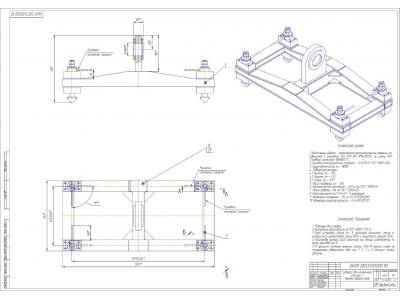
Traverses are used in transport operations for handling ILW packaging. Furthermore, the traverse type 2 is also used for transporting plates overlap canyon. Girders are used in the building 223, Kursk NPP (HTRO-III). Girders are designed for operation in a closed heated room at + 10 ° C ... + 35 ° C and relative humidity 80% at + 25 ° C. Category of premises in accordance with SP 12.13130.2009 "Definition of categories of rooms, buildings and outdoor facilities for explosion hazard" - B4.
Specifications
Capacity, t | 8 |
suspension method | Through the finger in the suspension crane |
The force on the handle locking mechanism, H | No more than 120 |
Seismic category NP 031-01 | II |
Safety category NP 001-15 | 3H |
Category of SP AS-03 | II |
Climatic performance according to GOST 15150-69 | UHL4 |
Description of the construction
The yoke is welded frame fixed thereto with locking mechanisms.
Principle of operation
Traverse, suspended on a crane, lowered onto the package CAO, locking key design makes it easier to hit them in the corner fittings package. Locking mechanism takes place by turning the key through 90 °. Rotation is carried out manually (traverse type 1) or electrically driven, remotely (type 2).
Strength calculations and seismic
As part of the verification calculation for the design of traverses (type 1), the following types of calculations must be performed:
- calculation of the static strength;
- calculation of seismic impact.
As part of the calculation of the static strength of the two kinds of calculations have been carried out:
1) to the maximum (limit) in the load operating state 16t (two-fold of the total load (rated) load in 8t);
2) to the special load 56T (sevenfold from full load (rated) load in 8t).
Seismic category traverse NP-031-01 - II. According to the classification of "earthquake-resistant design standards of nuclear power plants", articles belonging to seismic category II should continue to operate after the passage of earthquake intensity up to and including the PP. Thus earthquake resistance calculation was made on a load mode Nue + PP values are taken from spectra on the mark setting response +20,000 crane.
Calculated on the static strength and seismic performed using module APM Structure3D, which is part of system 13 APM WinMachine XE.
The computational model to traverse APM Structure3D, under normal operating conditions is shown in Figure 5.
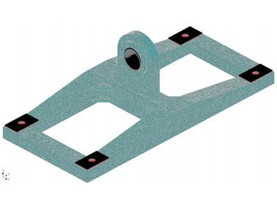
In the construction of the computational model used 10 end node element (tetrahedron). This element has three degrees of freedom at each node in the form of projections displacement nodes at coordinate system axis.
Kinematic boundary conditions were specified as a ban on all movement of points on the surface of the eye holes.
Power boundary conditions were given as force N 160000, distributed along the inner surfaces of the holes for which are fixed straps.
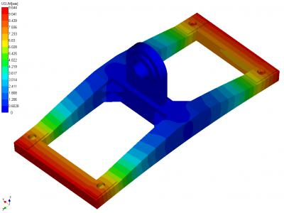
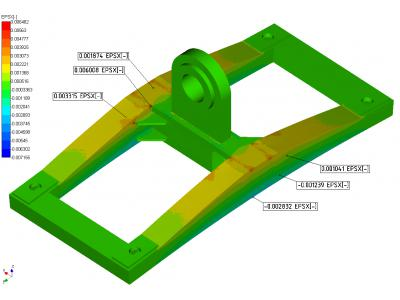
Calculation results of the stress-strain state traverse presented in Figures 6 and 7.
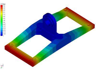
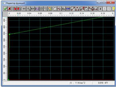
In nonlinear static based on the maximum loads during emergency operation conditions adopted bilinear model elastoplastic material behavior. Based on the characteristics of the material used in the calculation were asked deformation diagram (Figure 8)
Kinematic boundary conditions were specified as a ban on all movement of points on the surface of the eye holes.
Power boundary conditions were given as force N 560000, distributed by shelfplasty installed at fixing gripper mechanisms.
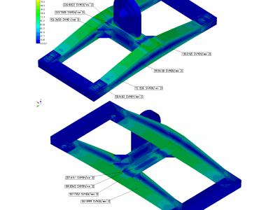
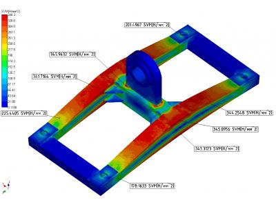
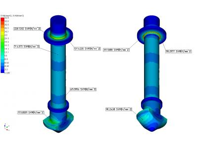
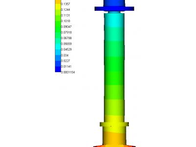
Calculation results of the stress-deformed state in the nonlinear static traverse based on ultimate loads during emergency operation conditions are shown in Figures 9 - 11.
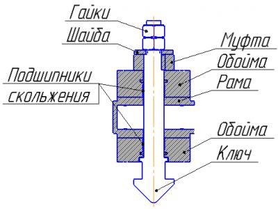
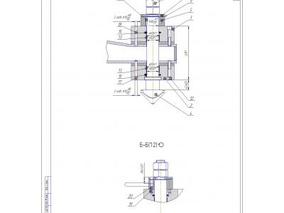
The same calculation was performed elements gripper mechanism at maximum loads during emergency operation conditions. The load of the weight of cargo (container) is transferred to the frame through the switch, a washer, sleeve and the clip (see Figure 12). The most responsible and the loading mechanism elements are key and washer.Therefore, it is for them evaluated strength.
The calculation model created for determining the stress-strain state of a key and a washer is shown in Figure 13.
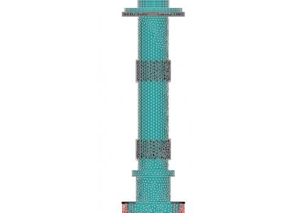
The kinematic boundary conditions were set as prohibition key movements along the axes x and y in places of plain bearings installation and prohibiting movement along the z axis washer in place of its contact with the clutch.
Power boundary conditions were given as force 140000 N is applied to the key at the point of contact with the container.
Calculation results of the stress-strain state of the gripper elements of the mechanism shown in Figures 14 and 15.
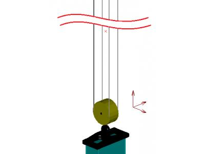
Traverse for calculating simulated seismic impact together with the container and the crane suspension ropes. The computational model is a three-mass system (traverse, cargo and crane suspension) hanging on four ropes and is shown in Figure 16. In order to obtain the correct result, the mass of all elements of the model are the actual values.
Kinematic boundary conditions were specified as a ban on all movement of rope attachment points to the tap.
Power boundary conditions, in accordance, are given as:
- 160000 H force distributed over shelfplasty installed at fixing gripper mechanisms;
- acceleration of 3.38 m / s 2 along the horizontal axes (x and y);
- acceleration of 1.89 m / s 2 along the vertical axis (z).
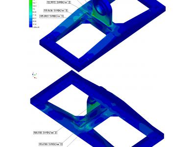
Calculation results of the stress-strain state traverse at seismic impacts are shown in Figure 17.
Analyzing the results of the calculation, we concluded that the strength elements to traverse the calculation load limits under normal operation conditions, under emergency operating conditions and seismic loads is provided.
Calculation crosspiece (type 2) was performed similarly.
conclusion
In the course of project execution engineering departments SEC "APM" was developed and delivered to the customer the next set of documents:
TOR (based on the initial technical requirements);
Set of design documentation;
Calculation of structural strength;
Set of normative-technical documentation (program and methodology of tests, passport, operating instructions, repair manual, Tupolev TB-1, Polikarpov TB-2, spare parts list).


