UM Pneumatic Systems
 Simulation of multibody systems with pneumatic elements
Simulation of multibody systems with pneumatic elements
Program package Universal Mechanism includes a specialized module UM Pneumatic Systems, which contains tools for simulation of models with pneumatic elements. The following elements are available in the current version of the module:
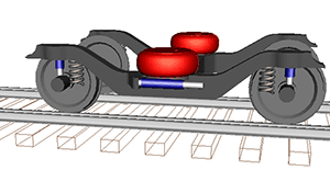
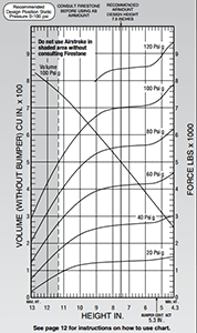
- Air springs
- Rigid chambers
- Pneumatic lines
- Orifices
The following AS models are available:
- Tabular model: the description of force element includes tabular experimental data on force and volume
- Nishimura model
- Berg model
- Thermodynamic model
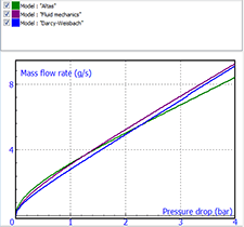
Three mass flow rate versus pressure drop models for pneumatic lines are implemented:
- "Atlas"
- Fluid mechanics
- Fluid mechanic
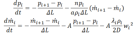
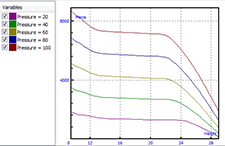
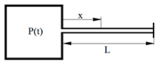
Time domain pipeline model
The dynamic model of a pipeline is described by a system of differential equations. The model allows taking into account transient processes and inertial properties of long pipelines.
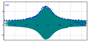
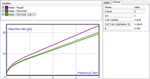
Orifice models
Similar to a pipeline, an orifice (nozzle, valve) is a connection between two nodes of pneumatic system. The mathematical model of an orifice includes a dependence of the mass flow rate on the pressure drop. The following orifice models are available in UM:
- Nozzle
- ISO 6358
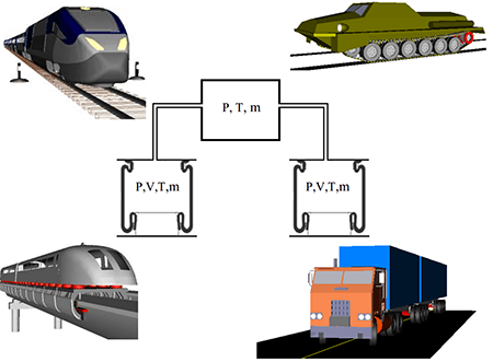
Pneumatic systems
A pneumatic system in UM is considered as a graph, which nodes are connected by edges. Each node of a graph corresponds to one of the pneumatic elements:
- Rigid chamber
- Air spring (AS)
- Simple node
The graph edges are:
- Pneumatic lines
- Orifices
Verification tests
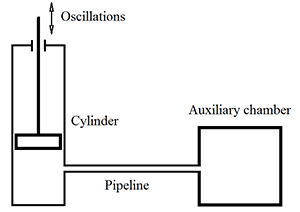
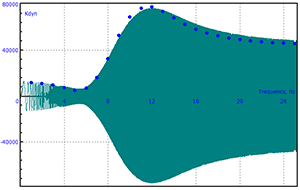
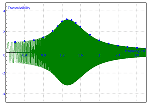
Case 1: Air spring connected by pipeline with auxiliary chamber
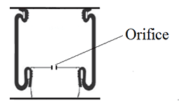
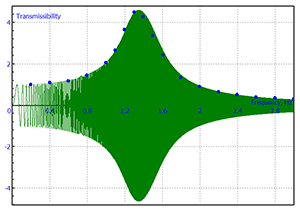
Case 2: AS connected by orifice with auxiliary chamber
Case 2: AS connected by orifice with auxiliary chamber
Case 2: AS connected by orifice with auxiliary chamber
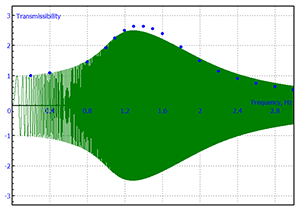
Case 2: AS connected by orifice with auxiliary chamber
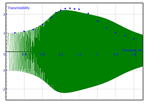
Case 2: AS connected by orifice with auxiliary chamber
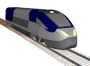
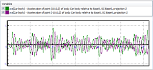
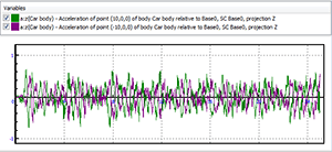
Simulation example: Heigh speed railway motor car