Calculations for seismic effects of NPP
pipelines using the Russian CAE-system APM WinMachine
Nuclear power plants - a complex technical system, consisting of a large number of different units and equipment, connected by pipelines. The total length of pipelines at nuclear power plants can reach tens of kilometers. The total cost is up to 10% of the cost of all the equipment of the station. Minor damage to the pipeline can lead to serious consequences. Therefore, ensuring the strength of NPP pipelines is one of the main tasks not only in the design and installation, but also in the process of operation. Pipeline structures should ensure operability, reliability and safety during the entire service life, as specified in the technical specifications or equipment passports. These requirements define a direct link between normative documents and strength of elements, efficiency, reliability and safety.
Evaluation of the strength of pipelines of nuclear power plants designed, manufactured and operated in full compliance with the Rules of AEC in the Russian Federation is carried out in accordance with the "Norms for calculating the strength of equipment and pipelines of nuclear power plants" (PNAE G-7-002-86) "[1] .
The reason for the durability for extending the life of the equipment is based on one of two provisions:
- on the actual operating conditions, the actual geometry of the elements and the actual mechanical properties of the materials used in the manufacture;
- Calculation of strength within the technical design of the product for a full service life, taking into account its extension.
The second position can be used if, in the past operation, there are no deviations from operating conditions, defects or reduction in size in excess of those envisaged by the project.
According to [1], the strength calculation must be carried out in two stages:
1. Calculation of the choice of basic dimensions;
2. Verification calculation.
As a result of the first stage of the calculation, the main geometric dimensions of NPP equipment elements are determined. When performing calculations for the selection of basic dimensions, design loads are the design pressure and pressure of the hydrotest.
After calculating the selection of the main dimensions, a verification calculation is carried out taking into account all design loads and all design operating modes. The main design loads are: internal or external pressure, the mass of the product and its contents, additional loads (weight of attached products, insulation of pipelines, etc.), forces from reaction of supports, temperature effects, vibration loads, seismic loads.
Verification calculation includes:
- calculation for static strength;
- calculation for stability;
- calculation for cyclic strength;
- calculation of resistance to brittle fracture;
- calculation for seismic impacts;
- calculation for vibration strength;
- calculation for progressive deformation.
As a result of the calculations, the values of stresses and deformations acting in the construction are determined, which are compared with the allowable values (calculated groups of stress categories) specified in [1].
The current norms [1] indicate the recommended methods for calculating the typical elements and nodes of the NPP pipelines based on the methods of materials resistance, the theory of elasticity and structural mechanics. Since the technique consists in the use of analytical "manual" calculation, its application is not without significant simplifications of the design, which lead to a breakdown of the calculated object into simpler elements. Further, the simplified elements are calculated separately, and the mutual influence of neighboring elements is taken into account by introducing the appropriate boundary conditions. Such simplifications introduce a large error in the calculation, so in the case of complex constructions this approach is not accurate enough. Sometimes a very difficult task is to determine the coefficient of stress concentration in the zones of sharp changes in geometry. Thus, there is a need to use numerical methods for modeling and calculating complex structures.
The automated calculation and design system of mechanical equipment and structures in the field of mechanical engineering APM WinMachine is able to solve complex tasks necessary to calculate the residual life or extend the life of the NPP pipelines. The APM WinMachine system implements algorithms for strength, thermal, and spectral analysis, which are necessary for the calculation of NPP facilities.
The actual for the moment is the calculation of the seismic strength. This is due to a number of major accidents caused by seismic impacts, one of which occurred on March 11, 2011 at the Fukushima-1 nuclear power plant in Japan and caused serious damage to the environment.
In the APM WinMachine system, the APM Structure3D module [4] is used to calculate the stress-strain state, stability, own and forced vibrations of parts and structures. This module allows you to create calculation models that closely describe the geometry of the nodes being calculated, and carry out the necessary analysis using the finite element method.
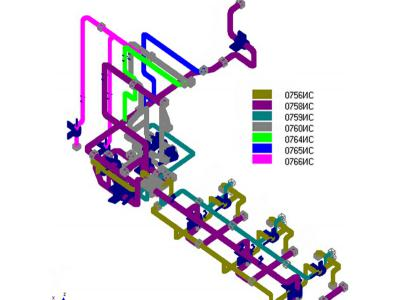
In Fig. 1 shows the part of the executive circuit and the geometry model of a typical pipeline for calculation for seismic impacts in APM WinMachine. The design model includes all the main elements of the pipeline.
It should be noted that it is important to consider the features of the implementation of the finite element method. When constructing the pipeline model in APMWinMachine, the shell finite elements of 3 and 4-node type VCT (element with discrete superposition of the Kirchhoff hypothesis) are applied. When using these types of grids, the rotational degree of freedom relative to the local Z axis can be activated by the user.
The finite element model of the pipeline, taking into account the separation of the sections of the scheme along layers (with additional coloring) is shown in Fig.

The design model of the pipeline must correctly reflect the boundary conditions of the estimated part of the system. It is necessary to distinguish the technological boundaries of the system, which are subject to seismic qualification, and the physical boundaries of the pipeline. So, if the qualified part of the system is limited to pipeline fittings, the pipeline model should be continued in such a way as to minimize the impact of the cut off part of the pipeline on the part subject to seismic qualification. The boundary conditions can be reproduced by creating appropriate forces or displacements on the boundary, as well as by using additional elements adjacent to the node under investigation and acting on it in a specified manner.
To the load-bearing building structures, the pipelines are fixed by means of various supports. The types of supports used in modeling the pipeline boundary conditions in the APMWinMachine system are shown in Fig. 3.
In accordance with recommendations of the IAEA, seismic resistance analysis of the NPP pipelines in operation is carried out using the so-called boundary seismic stability (IGS) method [2], [3]. The essence of the method is to determine the magnitude of the boundary seismic stability (parameter HCLPF). To calculate the magnitude of the boundary seismic stability of the HCLPF, the seismic reserve factor FS is used.
The methods used within the framework of the IAS for determining the seismic response of structures, systems and equipment (CSR) are selected depending on the dynamic characteristics of the object under consideration and the features of its support system. In the APMWinMachine system, the APM Structure3D module has two basic methods for determining the dynamic response in an earthquake:
- Static analysis, or the equivalent static load method, within the framework of the seismic qualification of CSR is used by specifying the static loading of the investigated structure by the inertial load distributed or concentrated in the nodes of the calculation model. In turn, the inertial load is defined as the product of the design weight load on a set of corresponding coefficients determined by SNiP or similar normative documents. Within the framework of the present technique, the application of the equivalent static load method is limited to equipment and components that have a first natural oscillation frequency above 20 Hz;
- The linear-spectral method assumes the modal analysis of the structure under consideration. At this stage, the shapes and frequencies of natural oscillations are determined up to the characteristic frequency f max corresponding to the acceleration of the zero period. Further, the system is loaded with inertial load for each of the calculated waveforms and for each spatial direction of the seismic action. In this case, for each of the forms of oscillation and the direction of seismic action, the total response of the system is determined: the distribution of internal forces, the movement and reaction of the supports, etc. The influence of higher forms of oscillations, not included in the main modal response, is taken into account by static correction. Special attention should be given to the various seismic displacements of rigid seals and structural supports. The resulting design response is computed using the CCSK summation rule (the square root of the sum of squares).
When using the linear spectral method, the floor response spectra are calculated as the initial seismic effect, calculated on the basis of the dynamic analysis of the main buildings and structures. For calculations of pipelines, as a rule, extended envelope spectra are used.
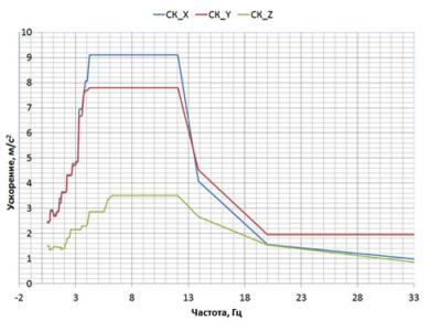
In Fig. 4 shows an example of a response spectrum diagram for a specific pipeline location marker. According to [1], for the calculation of pipelines and equipment, the relative damping value is taken to be 2% relative to the critical damping.

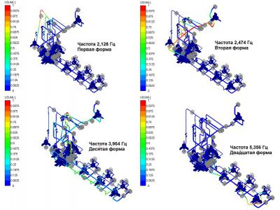
Below in Fig. 5 presents the various intrinsic forms of the pipeline oscillations obtained after the calculation in the APMStructure3D module, as well as the corresponding natural frequency frequencies.
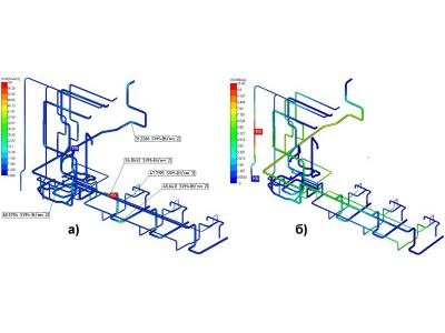
In the above example, the first natural oscillation frequency of the pipeline is 2,128 Hz. According to [1], the calculation for seismic actions was carried out by a linear-spectral method, taking into account 35 proper modes of the pipeline oscillations. Seismic loads were determined using the floor response spectra for the required mark. In Fig. 6 shows the results of the calculation of the pipeline under seismic influences.
The use of the APM WinMachine system allowed the construction of an accurate pipeline model in the short term, as well as the necessary calculations. This work shows that the APM WinMachine system is a highly effective tool for studying the stress-strain state of complex spatial structures and can be successfully applied to assess the strength of a pipeline of nuclear power plants under seismic influences.
In the near future, a finite element of a new type, TUBE (pipeline section), will be added to the APM Structure3D strength analysis module. This will reduce the size of the tasks to be solved and reduce the time spent on the calculation. Simplify the procedure for preparing models and performing analysis of calculation results. The new element is extremely relevant for modeling pipeline designs that are found in many industries.
Application of the APM WinMachine system for the calculation of nuclear power plant elements makes it possible to fulfill all the requirements set by the "Standards for calculating the strength of equipment and pipelines of nuclear power plants" (PNAE G-7-002-86), facilitates labor and allows analysis of the strength of complex systems under stringent constraints On the terms of design.
List of sources used
1. Norms for calculating the strength of equipment and pipelines of nuclear power plants (PNAE G-7-002-86). Moscow: Energoatomizdat, 1989. 525c.
2. "Safety Standards for Series No. NS-G-2.13, IAEA, Vienna, 2009;
3. "Seismic Evaluation of Existing Nuclear Power Plants", Safety Reports Series No. 28, IAEA, Vienna, 2003;
4. Certification passport of the software APM Structure3D (version 10.2). Registration number 330 of April 18, 2013;
Based on materials published in the journal CAD and graphics


