ArCADia-WATER SUPPLY INSTALLATIONS 2.0


PLEASE NOTE:
Program requirements:
In order to work, all industry-specific modules need a license for:
- ArCADia LT or ArCADia 10 or ArCADia PLUS 10 or AutoCAD 2013/2014/2015.
- If an industry-specific module is installed as an overlay for AutoCAD, ArCADia AC module is required.
System requirements:
- Pentium-class computer (Intel Core i5 recommended)
- 2 GB RAM minimum (8 GB recommended)
- About 3 GB free hard disc space for installation
- A graphics card compatible with DirectX 9.0 (a 1GB RAM card recommended)
- OS: Windows 10 PL or Windows 8 PL or Windows 7 PL


What is ArCADia-WATER SUPPLY INSTALLATIONS?
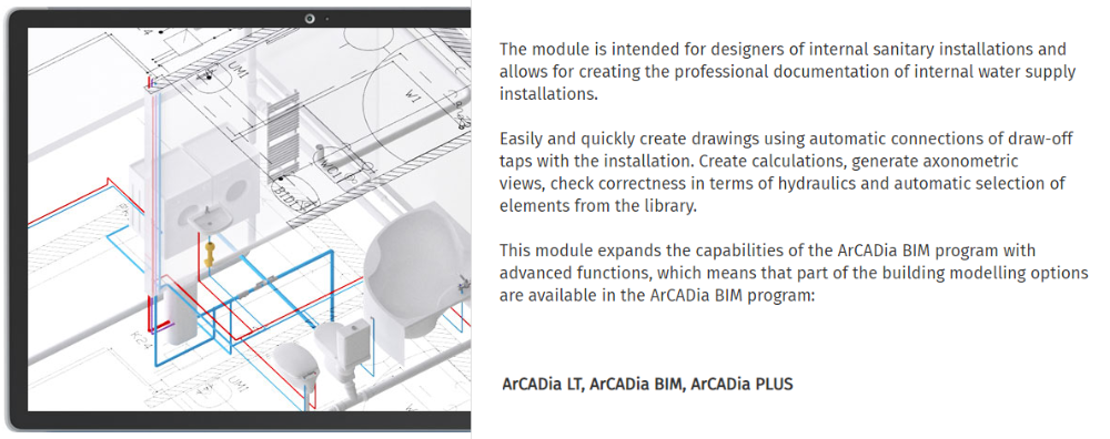
ArCADia-WATER SUPPLY INSTALLATIONS is an industry-specific module of the ArCADia BIM system, based on the ideology of Building Information Modeling (BIM). The program can be used to create professional technical documentation of internal water supply systems in a building. The program is intended for designers of internal drainage systems.
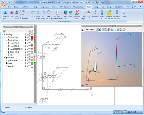
The program allows the object-oriented insertion of drawing elements on architectural background drawings, including the creation of design diagrams and the generation of three types of axonometric projections. In addition, the program enables the automatic selection of elements, taking account of user preferences (elements are selected from catalogues) and the automatic generation of reports and bills of materials or objects used in the design. Water supply systems can be designed on the plans of buildings produced in the ArCADia-ARCHITECTURE program and designed in a CAD environment in the form of bitmap or vector files. The user can use the library of elements used in water supply systems, which can be extended and adapted to their own needs in the scope of machinery used and pipeline material types. A user template can also be prepared, including the possibility to save personalised default settings for each program element and transfer them together with a design.
The program can be used to verify a designed system in terms of hydraulics and equipment selection.
FEATURES OF THE PROGRAM:
- Drawings of an internal water supply system are verified from the connection point, water metering unit and pipelines to the necessary fittings.
- Water outlets and water supply pipeline routes are marked.
- Risers and water distribution pipelines are selected from the extensive library of pipes made of various materials. A number of parallel pipelines with various functions can be run and connected at the same time.
- Fittings and devices are inserted from the comprehensive library of manufacturers (water outlets, stop and check valves, safety, fire and control fittings, metering devices, filters, mixers).
- The insertion of various types of equipment with individually set shapes and dimensions (devices for central preparation of domestic hot water, water heaters, pressure boosters).
- Automatic generation of a set of connection fittings, including the possibility to modify them.
- The drawing aids that allow easy and fast connection of a number of water outlets, continuous insertion of vertical and horizontal system section routes, as well as the modification of a number of system element levels at the same time, saving typical element systems, such as water metering sets in the program library.
- The insertion of a system drawn in a CAD environment and the transformation of lines into pipelines (objects of the ArCADia system).
- Automatic creation of the point and description numbering, including the possibility to edit them. The creation of user templates.
- Generation of the three types of axonometry (also partial) and the possibility to make it more comprehensible by the offsetting and shortening of a section in a single brief operation. The possibility to insert stop valves directly in the axonometry drawing, including their automatic consideration in the plan and listings.
- The calculation of total and partial pressure losses for all or selected water flow paths and selection of the least favourably located distribution point.
- The calculation of heat losses and pressure losses in circulation systems, including the possibility to determine the required parameters of the delivery head and capacity of the circulation pumps.
- Allowance for the hydraulic conditions in the calculation for a system with fire-fighting hydrant used.
- The verification of a system for correct connections.
- The automatic selection of system elements, allowing for the regulations in force.
- The generation of calculation reports, ready-made bills of materials, equipment and connection fittings included in a design for further processing.


