Liftopodemnik, Tuapse Krasnodar Territory
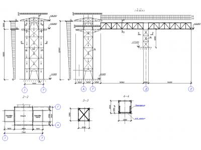
Strength calculation liftopodemnika the pedestrian bridge at the main and special load combination was commissioned by OOO "ChernomorStroyProekt". The calculation model created by means of APM Structure3D nucleus in accordance with the customer's drawings. In order to ensure that the conditions of strength, specialists of STC APM made some changes in the design.
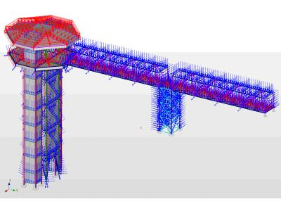
When calculating taken into account that the construction of these power factors are:
• own weight (simulated job multiplier dead weight);
• payloads on the overlap;
• Load of lifting equipment;
• snow loads;
• ice load;
• wind loads;
• seismic loads.
Loads the task was carried out in accordance with SNIP 2.01.07-85 * Loads and effects and SNKK 20-303-2002 Loads and effects; wind and snow load ( TSN 20-302-2002 Krasnodar region ) as well as with technical requirements.
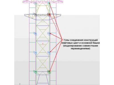
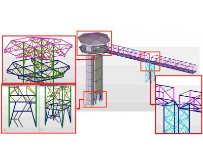
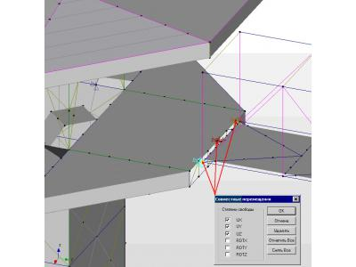
Modeling compounds constructions had several interesting points, as indicated on the pictures below
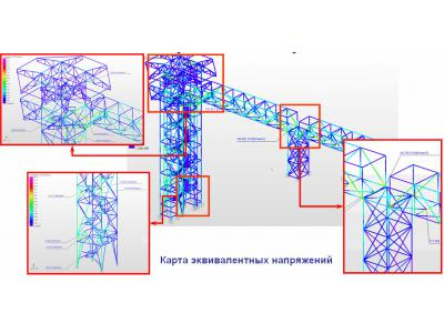
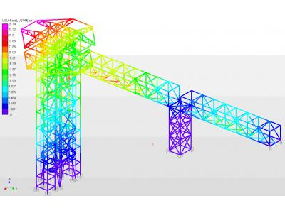
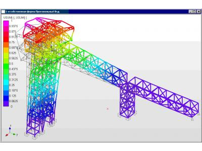
Maps are of equivalent stress for the most unfavorable combination of loads - combination of loads with seismic load on the axis X. The maximum stress 168 MPa, accounted for fastening the elevator shaft assemblies to the main tower. The maximum displacement of the effect of the combination of seismic loadings with load on X axis is 29 mm.
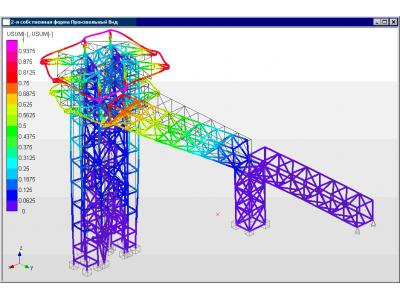
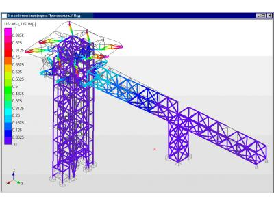
Checking elements SNP II-23-81 * performed to separate most loaded elements each form sections.
By card equivalent stress maximum stress is 168 MPa, which is less than the yield limit of the material (245 MPa). Thus, the strength condition is satisfied. Safety factor for the yield point is: n = 245/168 = 1,46.
Additional verification of SNIP II-23-81 * Steel structures for individual items showed that all the criteria for calculating utilization rates (reverse to the safety factor), as expected, less than one. Thus, we can conclude that the structure can bear the applied load.


