ArCADia-ARCHITECTURE 8.0

What is ArCADia-ARCHITECTURE 8?
ArCADia-ARCHITECTURE is an industry-specific module of the ArCADia BIM system, based on the ideology of Building Information Modeling (BIM). The program can be used to create professional architectural documentation. Above all, it is intended for architects and all who shape and restore building forms.
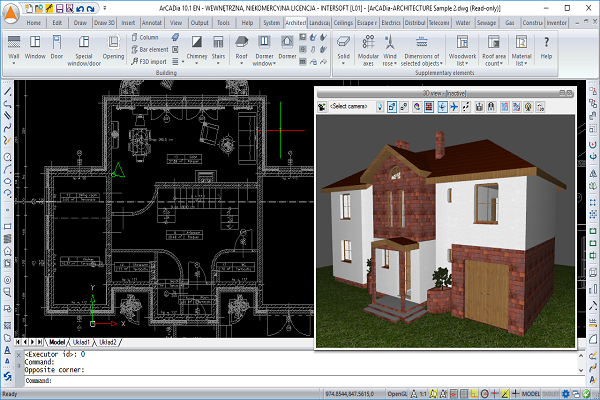
ArCADia-ARCHITECTURE is used for the object-oriented creation of professional architectural plans and sections, interactive 3D previews and realistic visualisation. The program features specialist architectural functions, such as: automatic cross-sections, automatic dimensioning or importing object shapes from other programs.
Features of the program:
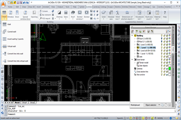
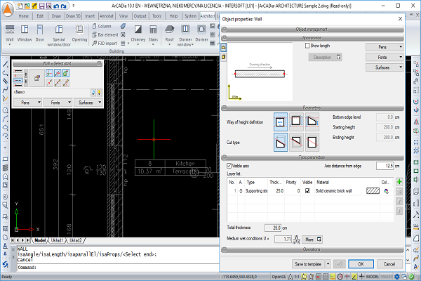
WALLS:
- The insertion of arch, single- and multi-layer walls.
- The possibility to transform a 2D drawing created from polylines or lines into the plan of single- or multi-layer walls, virtual walls or a foundation plan..
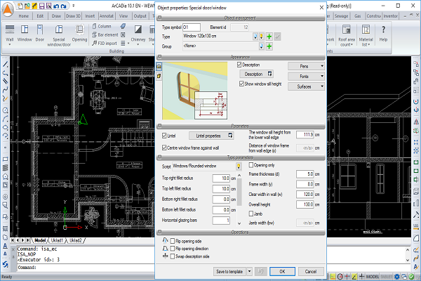
SCRIPT WINDOWS AND DOORS:
- The insertion of windows of various shapes (circular, triangular, with an arch, etc.), including the possibility to set horizontal and vertical division and define the visibility of windowsills or cut an opening itself (without a windowsill) in a wall in the shape of special windows (doors).
- The insertion of single and double arched doors, including additional side or top lighting.
- New windows have been added to the script library; unipartite, bipartite, and tripartite ones with the possibilities of entering mullions or vent windows.
- The following elements, among other things, have been added to the doors library: revolving, sliding, swinging, and evacuation doors.
WALL OPENINGS:
- The insertion of an opening of a set width and height in a wall from the left and right side (insertion at any height).
- The possibility to insert a recess of a predetermined depth.
FLOORS:
- The insertion of any floor by indicating its shape.
- The insertion of a floor on ground in rooms of the lowest level.
- Entering the holes in the ceiling automatically or by hand.
COLUMNS:
- The insertion of vertical and inclined steel columns.
- The insertion of a horizontal steel object.
- The insertion of a bar frame from a .f3d file, which is seen as one element but can be exploded and viewed as a single bar element (to be moved and edited separately).
- The multi-insertion of bar elements with defined quantity, spacing and the direction of insertion.
STAIRS:
- The creation of a spiral staircase inserted with or without a pillar.
- The insertion of single ramps or ramps with a landing.
ROOFS:
- The automatic and free insertion of pitched roofs, including a complete range of modification options (changing into a single-sloped or double-sloped roof, cha ging the height of a knee wall and inclination of any slope separately).
- The insertion of windows and openings in the roof.
- The insertion of dormer roofs (dormer windows).
- The insertion of a timber structure from the R3D3-Frame 3D program (roof slopes exported to R3D3-Frame 3D are structurally calculated, while the roof framework is returned to ArCADia-ARCHITECTURE).
- The insertion of roof hatches.
- Automatic or manual insertion of roof gutters.
- The insertion of drain pipes which automatically detect the gutter and the level of the terrain.
- Automatic or manual insertion of ridge tiles.
- The insertion of chimney cowls, ventilation cowls and fume cowls.
- The insertion of snow guards: snow fences, snow crushers and stoppers.
- The possibility to define the type of a roof before inserting.
- The tracking options are now available when inserting the roof.
- The possibility to insert a solar collector on the roof.
FOUNDATIONS:
- The insertion of a strip footing or any defined spot footing in the plan.
SOLID:
- Drawing any shape of a solid with a set height. The solid can be further used as a terrace, platform, mezzanine, and similar elements.
- The insertion of a solid of a specified width and height, e.g. as binding joists and beams, including the possibility to select an insertion axis or edge.
- Solids are inserted through a rectangular outline.
- Edition of solids by dividing them and creating any holes.
OBJECTS:
- Importing objects in the following formats: 3DS, aco and o2c.
- User-defined symbols (2D elements) can be saved in the program library.
- A project package, which is the possibility of moving the project with imported objects to a computer where the standard object library doesn’t contain these objects.
- The possibility to save an object from any of the system components of ArCADia in the library, e.g. the element created from spatial forms.
CROSS-SECTION:
- The automatic creation of a cross-section by indicating the cut line of a building, including the possibility to define elements visible in the cross-section.
- The insertion of a stepped cross-section with any number of folds.
- The automatic insertion of ring beams, locating them above the load-carrying layer of a wall (with set types of wall layers) in the floor void.
- Lintels visible in the cross-section are automatically inserted with the window and door joinery.
- The cross-section can be automatically and manually refreshed to accelerate the work over the design.
- Views can be exploded, maintaining element groups and support for the Project Manager.
- The possibility to show a cross-section of 3D objects. The option is turned off by default, which can be changed from the Project Manager window after switching on the light bulbs.
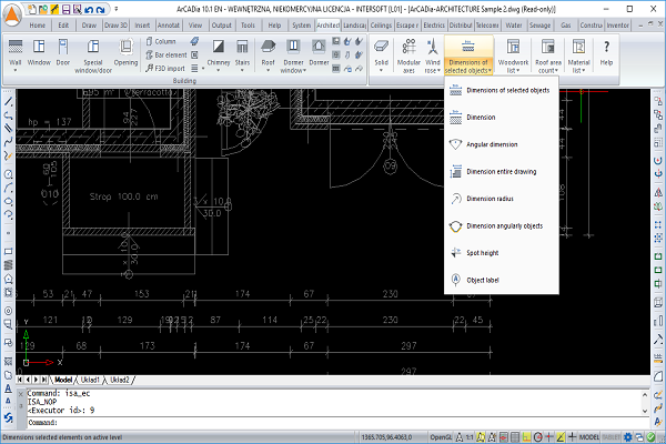
AUXILIARY ELEMENTS:
Dimensioning:
- The automatic dimensioning of the entire floor plan by selecting dimensioning lines (total external, external for protruding elements, rooms and walls, windows and frames, as well as openings).
- The assignment of dimensioning to objects, which enables automatic modification for all edits.
- The angular and radial dimensioning of walls.
- Dimensioning that indicates arch wall lengths.
- The possibility to insert a spot height in the floor plan and cross-section.
- The possibility to insert an element description (roof, floor, wall) both in the plan and cross-section. (Apart from the match, a flag with a bill of materials for an indicated element is also available)
- Full modification of the elements of the list, adding and subtracting materials and changes to the existing materials.
- Automatic description of the structure of the roof truss, element numbering showing the cross-sectional size and length of the element.
Listings:
- Automatically created listings of timber for timber structures inserted in the R3D3-Rama 3D program.
- Area and cubic capacity count. New bills that automatically add up the surfaces of: gross covered area, net and gross storey and building surfaces, as well as the cubic volume. The bills also include: the minimum plot area and roof data: inclination and ridge height.
- New bill of roof surface, in which the lengths of eaves, corners, roof valleys, ridges and roof edges will also be included, apart from the roof outlay and calculations of roof slopes.
- Automatic bill of roof accessories: lengths of gutters, ridge tiles and drainpipes, the number of caps and connectors for pipes and ridge tiles, as well as the number of cowls and snow guards. The possibility to choose which elements will be included in the bill.
- A bill of roof materials.
- Bill of materials of the objects that have been used thus far. A tally of the number of pieces, e.g. bricks, with the possibility of selecting packaging (pallets, packages, rolls), the ability to select the elements for which the list is inserted. Export of a single table of a list or several ones at the same time in a single file.
- An inserted bar elements list, both the ones defined in the design, and those imported from the R3D3-Rama 3D program.
Wind Rose:
- The possibility to introduce a ground floor and a symbol of the north arrow onto the cross section.
- The new version makes the compass rose dependent on the daylight analysis, coordinates the design’s location are provided or the city is indicated on the list, thanks to which rendering is calculated in the indicated bottoms and hours.
Communication with other systems:
- Object-oriented data exchange with the ArCon program (two-directional transfer of 3D objects written in program library).
- Export of a design trace to R3D3-Rama 3D, ability to transfer all the roofs of the design at the same time with all the modular axes joined in one grid.
- Import of the structure frame from R3D3-Rama 3D from a F3D file.
PLEASE NOTE:
Program requirements:
In order to work, all industry-specific modules need a license for:
- ArCADia LT or ArCADia 10 or ArCADia PLUS 10 or AutoCAD 2013/2014/2015.
- If an industry-specific module is installed as an overlay for AutoCAD, ArCADia AC module is required.
System requirements:
- Pentium-class computer (Intel Core i5 recommended)
- 2 GB RAM minimum (8 GB recommended)
- About 3 GB free hard disc space for installation
- A graphics card compatible with DirectX 9.0 (a 1GB RAM card recommended)
- OS: Windows 10 PL or Windows 8 PL or Windows 7 PL
RENDERING:
- Materials for each element with its properties are defined.
- Simple (fast and easy to use) or advanced rendering, including the possibility to define all necessary settings (lighting type and position, shadow softening, etc.).
- The new rendering method for outdoors and indoors Photon mapping).
- Two renderings can be calculated in different views: daylight and nighttime views.
- The rendering window is independent of the ArCADia-ARCHITECTURE program, which makes it possible to continue working on a design, as the visualisation is calculated.
- Multi-rendering, which is recording the views from predefined cameras.
- The notation of the building view with rendering as a single scene or from selected cameras as defined in the program.
- The ability to turn off the computer after a multi-record of rendering from the cameras introduced into the design.
- Daylight analysis with a date and time setting, thereby rendering a scene on the days that interest us.