Calculation of the strength of the cabin layout of aircraft
under the influence of overload 10g and 15g
introduction
The calculation was performed using the software - CAD / CAE «System of the automated calculation and design of mechanical equipment and structures the APM WinMachine 13 (APM system WinMachine 13).
Strength analysis performed in module APM Structure3D, which is part of APM WinMachine v.13 system. having a certificate of Conformity № ROSS RU.SP15.N00524 requirements of the following regulations:
• SP 20.13330.2011 (SNIP 2.01.07-85 * "Loads and effects"); • SP 14.13330.2011 (SNIP II-7-81 * «Construction in seismic areas"); • SP 16.13330.2011 (SNP II-23-81 * «Steel construction"); • SP 15.13330.2012 (SNP II-22-81 «Stone and reinforced construction"); • SP 52-101-2003 ( "Concrete and concrete structures without prestressing reinforcement"); • SP 50-101-2004 ( "Design and apparatus of the foundations of buildings and structures"); • SP 50-102-2003 ( "Design and installation of pile foundations"); • SRT 36554501-002-2006 ( "Wood and glued solid wood construction design and calculation methods."); • GOST R ISO 9127-94 ( "User Documentation and Information on the packaging in trebitelskih software packages"); • GOST R ISO / IEC 12119-2000 ( "Information technology. Software packages. To quality requirements and testing").
APM Structure3D module has a certificate of conformity № ROSS RU.SP15.N00524 from 15.08.2012, the attestation and certificate software tool №330 from April 18, 2013, issued by the Federal Service for Environmental, Technological and Nuclear Supervision (Rostekhnadzor).
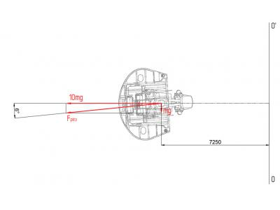
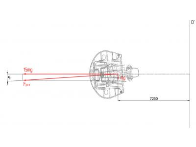
Objective: To calculate the strength characteristics of the cab structure and layout of the test study the possibility of its use as an aircraft cabin retrofit after its instrumentation equipment, installation of the centrifuge arm, and it works in rotation with overload up to 10g and up to 15g.
Verification calculation cab supporting structure is made on the basis of the technical task in accordance with the general principles of efficiency and reliability of structures according to the method of limiting states of the first group (state in which there is depletion of the bearing capacity (strength, stability or endurance) design with appropriate combinations of loads which may be accompanied by destruction of any kind, by converting the system into the mechanism, the formation of cracks, chains of plastic hinges et al.).
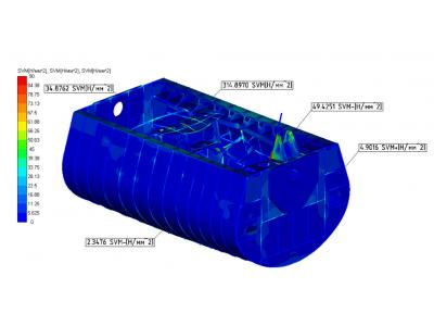
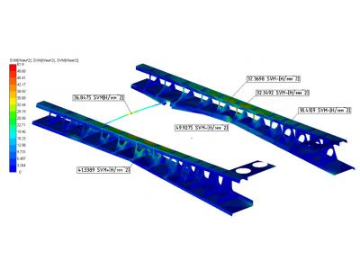
During static analysis calculation model are defined: basic reaction, internal force factors, stresses and deformations arising in elements of construction, estimates its static strength.
The values of the internal power factors in the model nodes, obtained from the results of a static analysis, were used as input when performing verification calculations compounds static strength.
Based on the results of the strength calculation has been given an opinion on the possibility of further safe operation of the centrifuge cabin layout, after holding the routine maintenance, as well as recommendations for strengthening the critical component of the article.
Engineered scheme
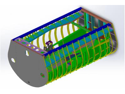
The product is a metal cab fortified with it instrumentation equipment. Bearing frame longerons and frames form a sheathed duraluminium sheets (plating).
Longerons (longitudinal elements set frame) perceived mainly longitudinal forces and bending moments, as well as a link between the transverse elements set - frames.
Frames are transverse chassis elements set attach cab predetermined cross-sectional shape, providing lateral stiffness, and perceived local loads and a rigid reinforcing skin.
Linings made of sheet aluminum alloy and is attached to the frame elements. Skin sheets are joined together end to end on frames.
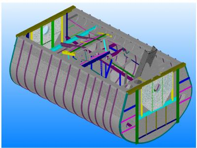
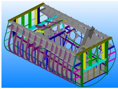
Finite element model
The construction of the finite element model to calculate the strength of the cab structure of the stand, as well as the equipment attachment points, performed in the software package APM WinMachine 13. This program allows you to build a model, a fair representation of the geometry and behavior of a real object, followed by FEM calculation.
When constructing a computational model used rod (beam), three- and a four lamellar, hexagonal and an eight volumetric finite elements.
Kinematic and force boundary conditions have been set in accordance with the technical documentation for the product.
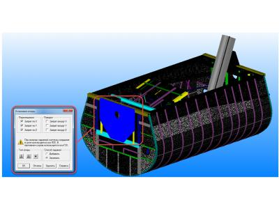
Kinematic boundary conditions and connections
Schematization conditions fixing the model assumes simulation constraints imposed by external and internal constraints on the position of the elastic system as a whole and the individual components. In modeling the behavior of the supporting structure is considered a variant of its fixation on a shoulder of the centrifuge. External communication systems reproduced by specifying restrictions on movement of supports on the global Cartesian coordinate system (Model GSK).
Internal communication model simulated the conditions of connection of individual constructions cab-tive elements. The approximation to the real conditions of a compound of structural elements is achieved by introduction into the calculation model fictitious (non-deformable) and removing the rods from their limitations for certain degrees of freedom.
The loading of the cab structure
The supporting structure of the cabin is under the influence of distributed systems of vertical and horizontal forces. Vertical forces created its own weight construction, equipment and pilot. Horizontal load on the structure creates inertia forces arising during rotation of the cab.
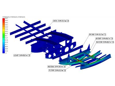
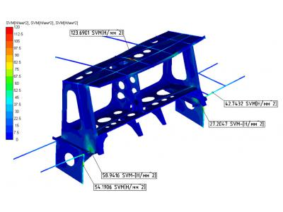
The calculation results
Carrying out the static analysis is performed on the module for calculating the stress-strain state, stability, natural and forced vibrations of parts and structures using finite element method - APM Structure3D, which is part of an automated system for calculating and designing of mechanical equipment and structures APM WinMachine.
conclusion
Thus, the work described indicates that APM WinMachine system can be used successfully to assess structural strength lethal devices.
Using APM WinMachine for such calculations enables to fulfill all the requirements for aircraft structures, making the work easier and saves engineers time.


