APM WINMACHINE FEATURES
BASE MODULE - APM DATA - APM GRAPH
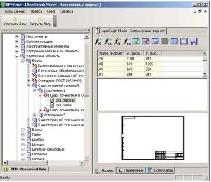
APM DATA
APM Mechanical Data Main features numerical data graphical data intergationwith APM WinMachine modules quick customization The database APM MechanicalData can be logically divided into two parts – the informational and thegraphical. The informational database contains numerical data characterizingqualities of the materials, tolerances and interference, as well as kinematic, energy,geometry and the other parameters needed for the operation of the other APM...
APM Mechanical Data Main features - numerical data - graphical data - intergation withAPM WinMachine modules - quickcustomization
The database APM Mechanical Data can be logically divided into two parts –the informational and the graphical. The informational database containsnumerical data characterizing qualities of the materials, tolerances andinterference, as well as kinematic, energy, geometry and the other parametersneeded for the operation of the other APM WinMachine modules and for the finding ofthe information required for the design decision making.
Geometric and numerical information is placed inthe graphical database. This allows you to perform drawings of the standardsdetails, assemblies,
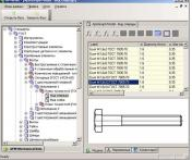
components, etc. With its help one may automate the drawing procedure, fill up the stamp, specification, etc. The graphical database functions together with the APM Graph editor. The models placed in the database are presented in the parametric form. Such presentation allows modifying the objects numerically and with the use of the analytic dependences. APM Mechanical Data consists of the following parts machine elements of the general purpose;- design elements; - rolled-products range; - materials; - normal sizes; - metrological data(classes of the accuracy, surface finish, tolerances and interferences) - electrical engines; - elements of the drawing design; - elements of the hydro- and pneumatic schemes; - elements of the structural drawing; - elements of the electrical schemes.The section “Machine elements of the general purpose” include graphical models and tables of the numerical parameters of the bolts, screws, shafts, bushes, screw nut, reducer body, bearing, oil indicators, glasses, rotation gears, washers, splines, split pins, keys, sprigs, screw nails, etc.
Conveyor belt drawing
The section “Normalsizes” has the table of the normal linear and angular dimensions as well asconical parameters. The selection is held from the normal lines with thedenominators Ra5, Ra10, RA20 and Ra40.
The section “Classes of the accuracy, surface finish, tolerances andinterferences” stores the metrology information.
The sections devoted to the electrical, hydraulic and pneumatic elementsschemes include notation conventions of the elements that can be used to makeall possible specialized schemes. These schemes are placed and scaledcomfortably on the drawings.
Formats, stamps, specifications and others atributes needed for the design ofthe technical documents are placed in the section “Elements of the drawingdesign”
Graphical andnumerical information about the engines of the different execution is in thesection “Electrical engines”. When using the section it is possible to makedrawings of the different engine’s projections in the arbitrary scale.
The APM Mechanical Data is the foundation, without which the operation of the APM WinMachine system is impossible, as it contains the information necessary for the normal operation of the other modules included in the APM WinMachine.
APM Mechanical Data is developed in such a way that it can maintain severalstandards. The partners of the Research and Software Development Center APM LTDperform customization of the database for national standards. They realize aswell the distribution of the software products under the APM WinMachine brandname abroad. Besides any user of the APM WinMachine system can fill on her own,for example, manufacturer or branch standards needed for the speeding-up of theengineering documentation design.
The high level ofthe automated design allows us to raise essentially the speed of the projectdevelopment due to the to use of the databases. Usually the details and theassemblies of the previous developments as well as standard elements are usedwhen designing new equipment. For the realization of these possibilities, it isnecessary to provide storage and a quick exchange of the design decisions ofthe previous developments and standard elements. In the system APM WinMachinethis function is performed by the informational and graphical database APMMechanical Data. It is arranged in the form of the separate module and isintended for the efficient preparation of the engineering documentation due tothe application of the parametric models of the standard elements and of theassemblies.
APM GRAPH
APM Graph is intended for performance of the graphical part of thecomputer-aided preparation of design documents. It is an integral part of theAPM WinMachine system, but it can be used independently. APM Graph representsa 2D graphics editor, which can be successfully used to design a graphical partof design documents in different engineering field, science, architecture andconstruction.
A drawing is the base of the designed machine elements. As the majority ofthe system modules allow to get a drawing of the designed part at the output,then for the final drawing design in the form of the document it is necessaryto finish it off and to get a firm paper copy. The APM Graph graphic editor,that constitutes a part of the APM WinMachine - performs these andothers functions.
APM Graph as an element of the computer-aided design system
APM Graph is intended for performance of the graphical part of the computer-aided preparation of design documents. It is an integral part of the APM WinMachine system, but it can be used independently. APM Graph represents a 2D graphics editor, which can be successfully used to design a graphical part of design documents in different engineering field, science, architecture andconstruction.
It can be efficiently used to prepare initial data during operation of APMWinMachine separate modules. For this purpose each application program is ableto import graphical information.
APM Graph possibilities - In order to draw objects there is a set of primitives such as a line, acircle, an arc, a point, a spline, a polygon etc. Objects can be drawn both ina free mode and combined with other objects: parallel, transversely,tangentially etc. When redrawing primitives, it is possible to snap to thereference points (ends of lines, centers of arcs and circles etc.), the middleof a section, intersections of objects, as well as drawing objects tangentiallyor normally with respect to the earlier created objects etc. There are several representations for each primitive. Depending on thespecified parameters, geometric relations between the objects can be fixed andviewed in the course of editing. Exact digital parameters of primitives can beset in the dialog box. APM Graph provides for commands, which can be used to draw linear, angularand radial dimensions. Dimensions can be drawn both in automatic andsemi-automatic modes. The possibility of dimensional chains calculation isfulfilled. Dimensions can be easily edited and modified. It is possible to settolerances on linear and angular values. The tolerance values are read from theAPM Mechanical Data library.

Pneumatic - hydraulic drawing
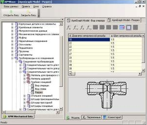
Drive unit standard element database
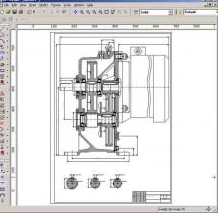
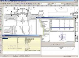
Assembly drawing
The built-in line type editor is available to draw objects with differenttypes of lines. The developed line types can be saved to file and loaded laterin other drawing. When entering a text it is possible to format a paragraph: to set indents,intervals, aligning, tilt angle. Hatching of areas is carried out by three different options: choosing one object out of the contour, choosing all objects of the contour, setting a pointinside the contour; in this case hatching of different types is used:flood fill, gradient fill, line image, predefined and textured fill, when *.bmpor *.wmf image file is used.
It is possible to draw different types of special symbols: tolerances, base symbols, roughness symbols, extension lines and special signs.
In order to connect lines and arcs, fillets and bevels can be createdaccording to different types of parameters. The drawing-graphics editor has the capability of graphic symbols direct drawing, fulfilled according to the valid All-Union State Standards of drawingup graphic documents. These symbols are used as symbolic notations of the part surface finish, engineering specifications for the surfaces, as well as of somespecial elements, such as welding joints etc. The table editor is convenient to draw up design documents, which significantly facilitates an effort of drawing up engineering documents,containing tables of different forms and sizes. By means of this editor a tableof arbitrary content can be created, an appropriate line type can be chosen andfields can be filled with text data. Objects of a drawing can be edited by different means: moving, copying,rotating, zooming, mirroring, creating rectangular and circular arrays,shifting objects etc. It is possible to break lines, arcs, circles or splinesin a point or between two points, as well as to perform truncation andalignment of any objects.
To make work with a drawing more convenient, the provision is made for operation with blocks. The block is a set of objects which can be worked with as a single object. It is possible that the block should be created from both separate primitives and other blocks. Blocks can be saved in a separate file toorganize libraries of structures and their elements.
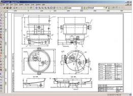
Stove-busket general drawing
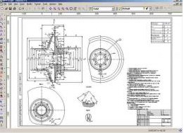
Rotary pump wheel
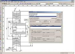
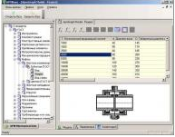
worm wheel parametric model
When working with a drawing it is convenient to place objects in differentlayers. By means of the layers manager one can control switching on/off andlocking/ unlocking the layers, as well as set a corresponding line type.
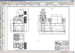
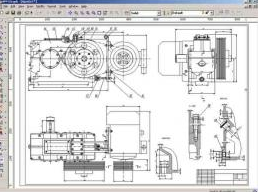
Reduction gear motor drawing