Strength calculation of steel structures attic of LSTC
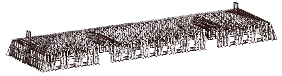
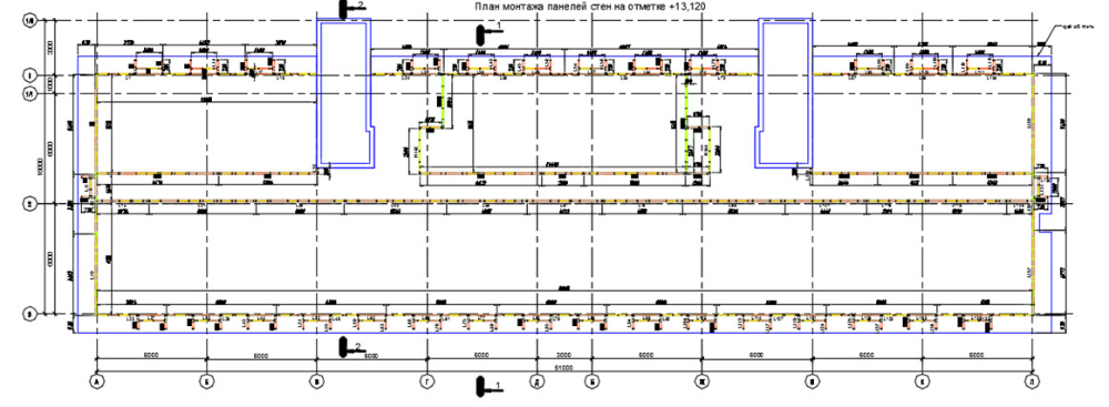
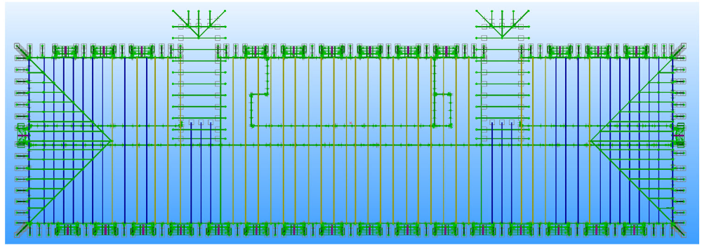
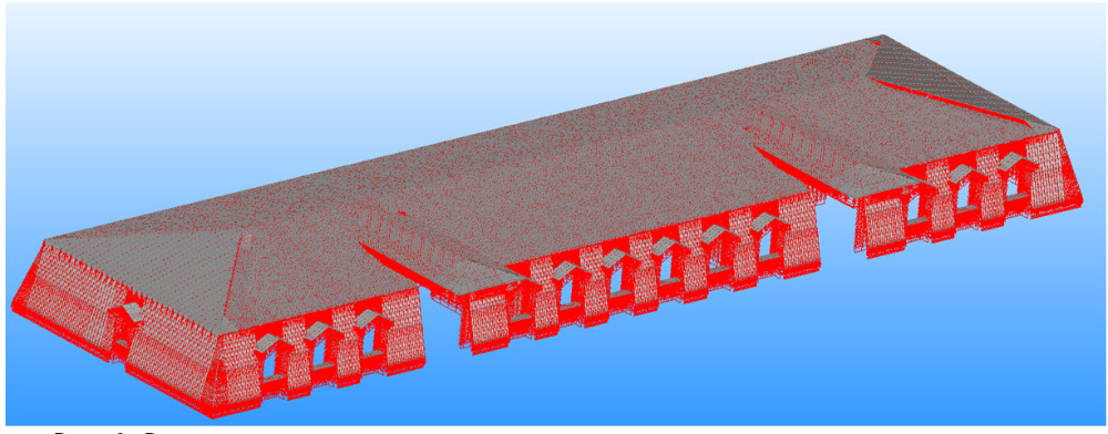
The computational model Garret is a one-story structure of rectangular shape, the elements of which are made of light steel thin-walled profiles (LSTC), with plan dimensions 51000h16000 mm, the height of floor to the bottom of roof trusses - 3100 mm, consisting of the following structural elements: a frame supporting walls, roof trusses, roof and parapet panels and windows. All frame members are fastened together by means of self-drilling screws (tapping screws).
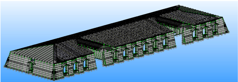
Model metal created under c architectural model, delivered to the customer.
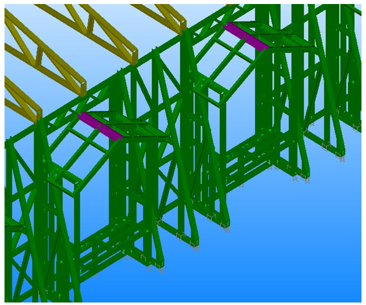
Metal frame of the attic of the building is made of Svjaseva scheme. Rack wall panels and trusses made of hinged support. Stability and performance frame of the building as a whole is provided by the system connections in the wall panels. Stability of the top chords of trusses provided releasably wooden crate. At the time of application design loads all of these elements are considered to be mounted according to the draft.
Load, impact and combinations thereof
load values were set in accordance with the joint venture 20.13330 Loads and effects, SP 14.13330.2011 Construction in seismic areas.
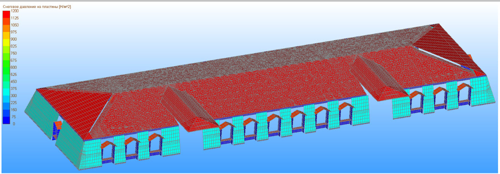
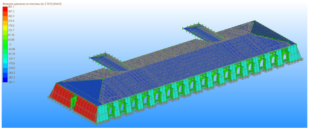
Uploading structure carried by several types of loads: regular (own weight of the structure, coating weight); snow and wind, according to the construction area; singular (seismic impact zone corresponding to seismic balls 7). After all the loads were composed by linear combinations of loads to which each of the loadings included with the corresponding coefficients (coupling coefficients, reliability coefficients for the load responsibility for safety factors).
The calculation results
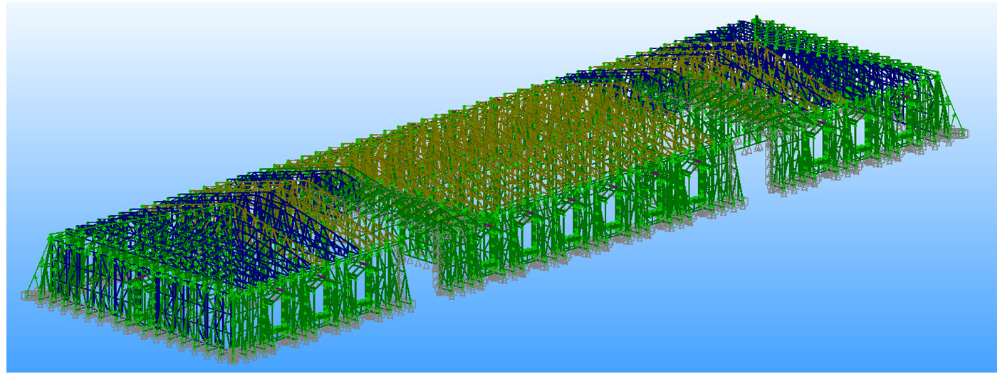
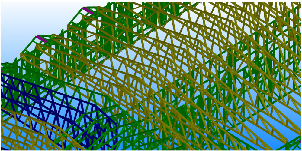
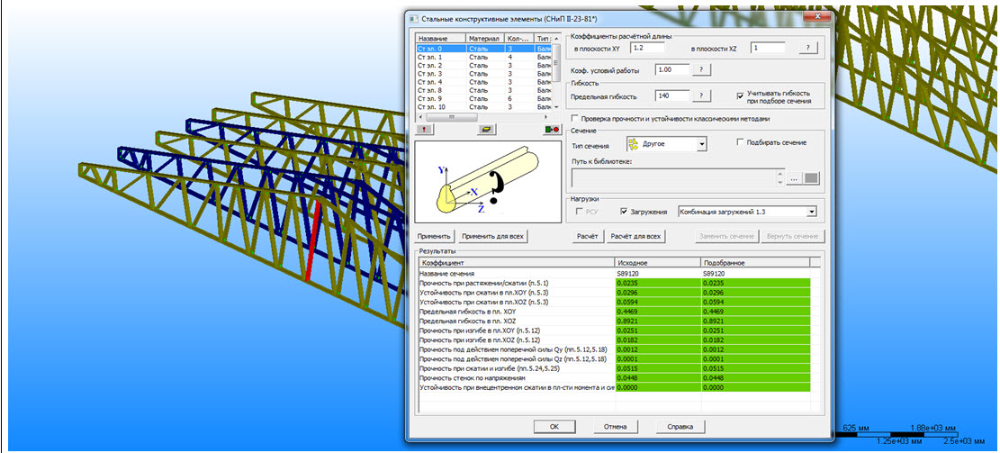
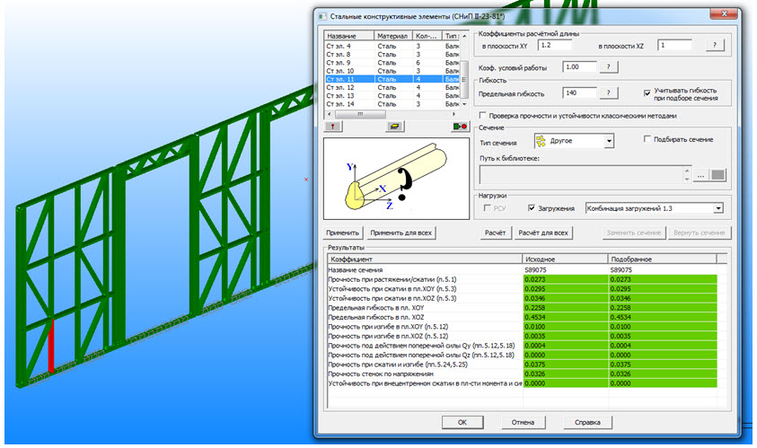
Obtained during strength calculation maps stress and strain state at the respective design loading embodiments set forth below.
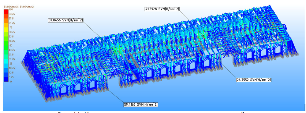
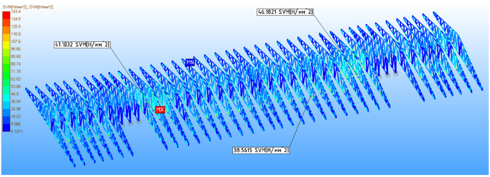
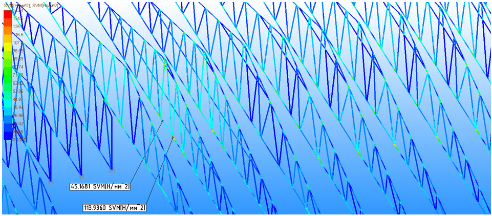
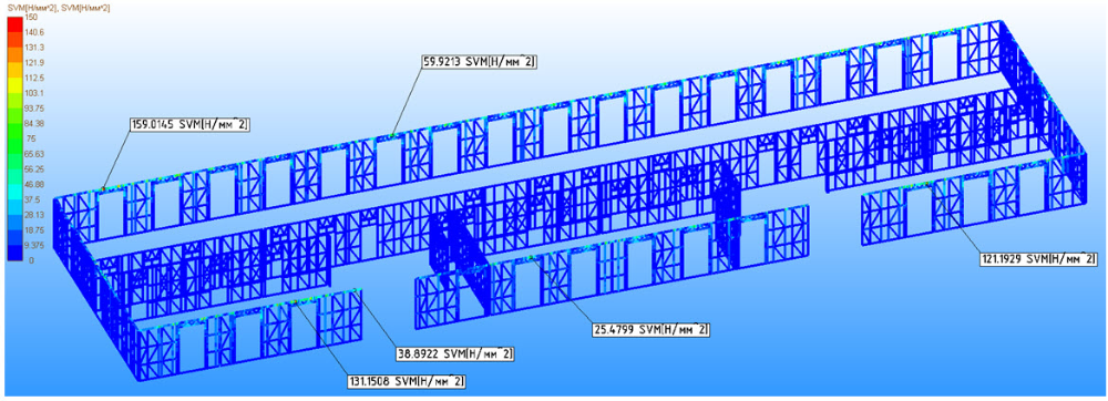
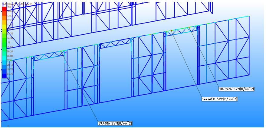
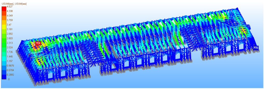
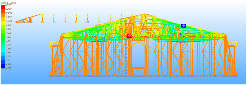
The analysis of the results of the calculation of the stress-strain state structure showed that the above project complies with Russian standards 16.13330.2011 JV, JV 20.13330.2011po criteria strength, rigidity and stability, and the attic structure is able to bear her load applied to the appropriate areas of construction. |


