C3d toolkit
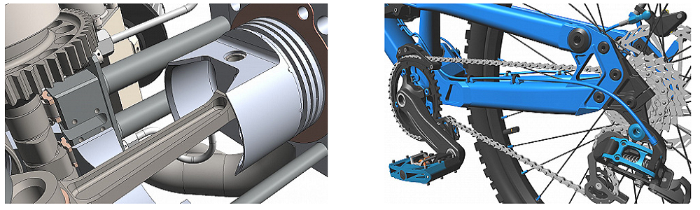
C3D Toolkit is a specialized tool for software developers, which includes several basic components responsible for constructing a geometric model, managing the constructed model and performing geometric calculations. It can be used when creating programs, the most famous class of which are computer-aided design systems.
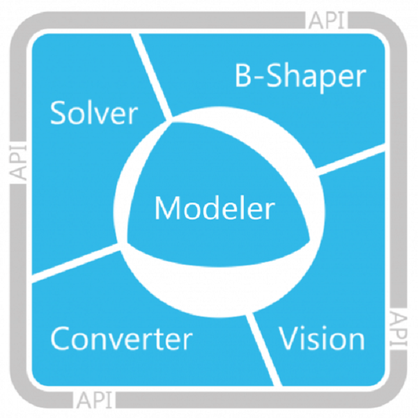
C3D Toolkit combines the most important modules for CAD development:
- C3D Modeler Geometric Core: Constructs a geometric model and provides geometric calculations
- C3D Modeler for ODA: allows members of the Open Design Alliance (ODA) to work with the functionality of the C3D geometric core using the ODA API
- C3D B-Shaper Module: Converts polygonal models to geometric models with boundary representation (B-Rep)
- C3D Solver parametric core: overlays geometric elements of relationships expressed in the form of equations and inequalities
- C3D Vision visualization module: provides high-quality visualization of the geometric model and provides interaction with the engineering software interface
- C3D Converter exchange module: supports data exchange with other systems
- improve product functionality
- quickly create a 3D product based on an existing 2D system
- reduce own development costs
- increase the reliability and speed of the software product
The delivery set includes dynamically connected libraries, auxiliary files for ensuring work in various software development environments, demo applications in source codes and technical documentation.
The delivery set includes dynamically connected libraries, auxiliary files for ensuring work in various software development environments, demo applications in source codes and technical documentation.
To build a geometric model are used:
- solid modeling
- surface modeling
- wireframe modeling
- direct modeling
- modeling sheet metal bodies
- hybrid modeling
- boolean operations
- symmetry operations
- cutting operations
- rounding and chamfering ribs
- thin-walled body operations
- face avoidance
- building stiffeners
- bending operations
- stamping operations
- building blinds
- direct editing operations
Elements of the geometric model can be moved, rotated and scaled.
One of the features of the geometric core of C3D Modeler is its open architecture, which allows you to increase its functionality. Developers can create their own objects, inheriting them from the objects of the geometric core.
C3D Modeler
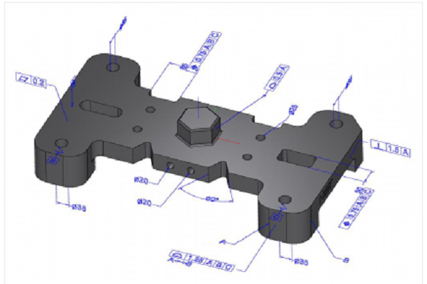
The geometric core of C3D Modeler allows solving 2D and 3D modeling problems in developed applications. The module is responsible for constructing geometric models and provides some geometric calculations.
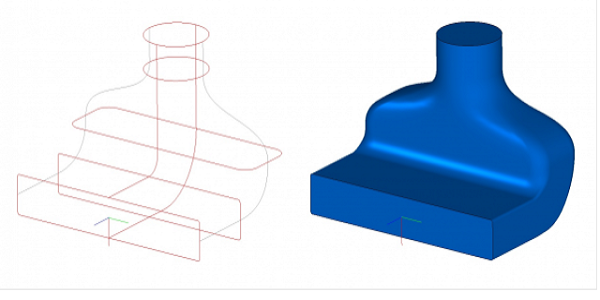
To describe the shape of the modeled object, the C3D Modeler geometric core uses a boundary representation, while the geometric model is built from three-dimensional bodies. Surfaces and curves are used to build bodies in 3D. Then the bodies are grouped into assembly units, from which assembly units of the next level can already be built.
Geometric calculations available in C3D Modeler:
- triangulation construction
- building flat projections of a geometric model
- calculation of surface area, volume and inertial characteristics
- definition of collisions of model elements
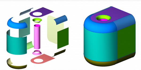
In addition to the boundary representation, the geometric core supports the polygonal representation of the geometric model. The construction of a polygonal 3D model is carried out according to its boundary representation using triangulation. Such a model has a similar structure as the model in the boundary representation. Elements of polygonal models are approximation objects built from plates and polygons. Such models are used for calculations and visualization.
Modeling complex bodies:
- extrusion
- rotation
- trajectory note
- Boolean body operations
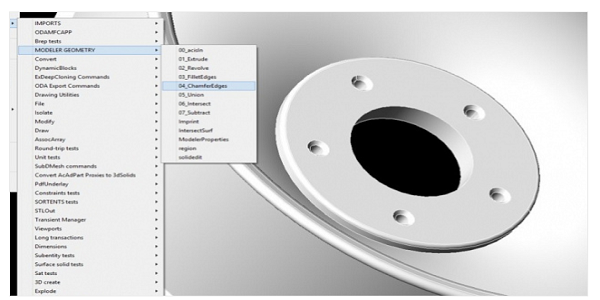
- chamfering and rounding
- building thin-walled bodies
C3D Modeler for ODA
C3D Modeler for ODA provides seamless integration between the C3D Modeler geometric core and the ODA platform, providing members of the Open Design Alliance (ODA) with access to 3D solid modeling functionality through the standard OdDb3DSolid API.
C3D Modeler for ODA is a lightweight version of the C3D Modeler geometric core and supports the following functionality.
Creation of elementary bodies:- ball
- tor
- cylinder
- cone
- block
- wedge
- prism
- pyramid
C3D B-Shaper
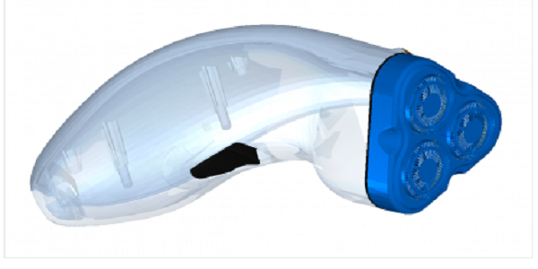
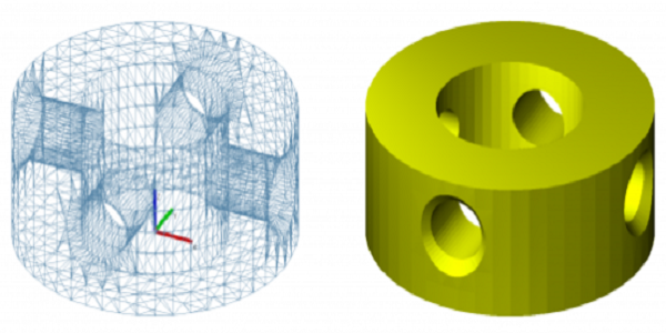
The C3D B-Shaper module converts polygonal models to geometric models with a boundary representation (B-Rep). As a result of the execution of the algorithms, the user can edit the resulting model with the usual solid-state tools of the CAD system, significantly reducing the complexity and amount of data.
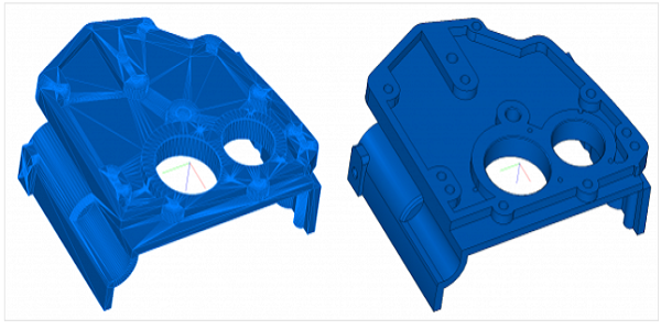
The C3D B-Shaper module opens up the opportunity to work with polygonal models in MCAD, AEC, BIM class systems. The use of the module allows you to speed up calculations, simplify visualization, ensure fast and high-quality formation of flat projections, and thereby increase application performance when working with large projects.
Applications for the C3D B-Shaper:
- Work in CAD and BIM-systems with polygonal models from catalogs of finished and standard models of parts, elements of buildings and structures
- Reverse Engineering: Editing 3D Scan Models
- Processing the results of topological optimization in CAE systems
- Grid smoothing, decimation and compression algorithms in computer graphics
Work with the module is carried out through the API. There are two options for its use: fully automatic and interactive.
The following functions are available to developers:
- SetTolerance surface recognition accuracy control
- SegmentMesh polygon mesh segmentation
- Segmentation Editing: Combining UniteSegments , Separating SplitSegment, and Other Methods
- Reconstruction of a surface of a certain type on the FitSurfaceToSegment segment
- Building a Model in the CreateBRepShell Boundary View
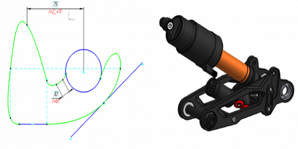
C3d solver
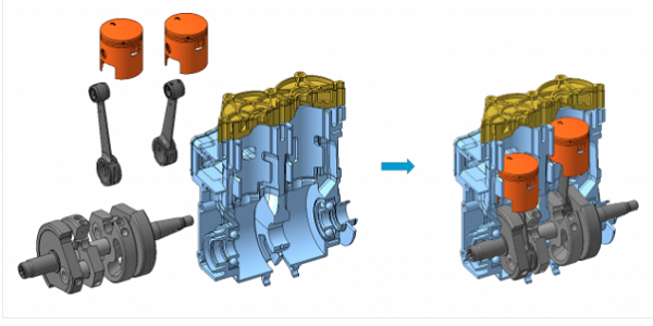
The C3D Solver parametric core connects the elements of the geometric model with the help of sizes and constraints and ensures the preservation of the specified relationships when resizing, model parameters, moving individual model elements or making other changes to the model geometry.
Relations between objects are described by geometric constraints, which can be dimensional and logical. Relations are superimposed on two-dimensional (2D) and three-dimensional (3D) objects.
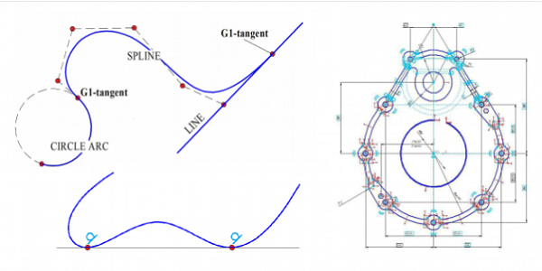
Scopes of C3D Solver:- creation of two-dimensional parametric sketches with control sizes and restrictions
- positioning assembly unit bodies using mates and dimensions
- rebuilding the model while maintaining the mates after making changes to the model
- modeling of mechanisms
- three-dimensional frame structures
Logical restrictions supported by C3D Solver:
- coincidence of objects (2D and 3D)
- point match (2D)
- alignment (3D)
- touch (2D and 3D)
- equality of lengths (2D)
- equality of radii (2D)
- geometry fixation (2D and 3D)
- fixation of length and direction (2D)
- spline fixation (2D)
- point on the curve (2D)
- parallelism (2D and 3D)
- perpendicularity (2D and 3D)
- horizontal (2D and 3D)
- verticality (2D and 3D)
- mirror symmetry (2D and 3D)
- cam mechanism (3D)
- gear transmission (3D)
- gear rack (3D)
- dependencies in the form of black boxes (3D)
- linear and angular patterns
Size Limitations Supported by C3D Solver:
- distance (2D and 3D)
- directional distance (2D)
- angle between lines and planes (2D and 3D)
- radius (2D and 3D)
- formation and solution of a constraint system (2D and 3D)
- geometry manipulation / object dragging (2D and 3D)
- diagnostics of solvability of constraints (2D and 3D)
- degree of freedom analysis (2D)
- clustering assembly elements (3D)
- API call logging (2D and 3D)
C3D Vision
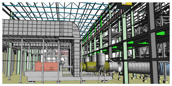
The C3D Vision visualization module is required to configure the graphical interface of engineering software and visual display of geometric models in it. The component controls the quality of rendering models using mathematical, software and hardware tools, as a result of which the speed of working with large drawings and assemblies is increased.
Application of C3D Vision in software development opens up new possibilities for managing three-dimensional scenes, allows you to use the finished tree for building 3D models, animation, interactive scene manipulation tools operating in the user-computer mode, as well as virtual devices that are an integral part of modern engineering software interface.
C3D Vision is closely integrated with the geometric core of C3D Modeler: to automatically generate a scene graph based on a mathematical model, it is enough to call only one function. Calculation of the polygonal model, search and drawing of objects can work both in synchronous and in multi-threaded mode.
C3D Vision operates with polygonal models. The scene is presented in the form of a graph and is divided into segments. Each segment has its own characteristics:
- absolute and relative matrices
- geometry reference
- array of geometry representations
C3D Vision implements a number of integrated solutions that simplify the interaction of an engineering software developer with a visualization module:
- Slots and signals for communication of C3D Vision objects, which reduces the development code
- Metadata from which you can find out the name of an object and its properties or check whether an object inherits a specific class
- Native events - a simplified event model for working, for example, with events from input devices
- Section with a plane or several planes using OpenGL tools with the option of closing the cutoff point
- PMI objects (comments and sizes)
- Defining objects under the cursor
To achieve maximum performance indicators, the visualization module controls the accuracy of the calculation of the triangulation grid and supports LOD detail levels when working with static graphics, plus a number of settings for the dynamic scene:
- hiding edges when rotating a 3D model
- polygon smoothing (antialiasing)
- removing minor scene elements
- delete items outside the scene
- vertical synchronization, in which the scene refresh rate is synchronized with the frame refresh rate on the monitor screen
- acceleration of graphic calculations through the use of video card capabilities
Available shaders:
- object selection
- shadow drawing
- specularity
- processing large amounts of data generated by 3D models in massively parallel computing systems
- loss of image quality when scaling a 3D model
- lack of visualization support in the dynamics of the account
- unsatisfactory work with visualization directly in computing nodes
- insufficient use of hardware capabilities for visualization
- requirement for visualization with a large number of processors
- problems supporting the application of different types of video adapters
C3d converter
The C3D Converter exchange module is responsible for reading and writing 3D models in files of neutral formats and in their own formats of various geometric cores. Together with information about the geometric shape of the modeled object, it is possible to transmit information about the author, the name and designation of the object, as well as other notations.
C3D Converter reads and writes files transferring models in the boundary representation in the formats:- STEP with PMI (AP203, AP214, and AP242 Protocols)
- IGES (v.5.3)
- Parasolid X_T, X_B (read v.29.0 / write v.27.0)
- ACIS SAT (read v.22.0 / write v.2.0)
C3D Converter reads and writes files transferring models in polygon representation in the following formats:
- STL
- VRML (v.2.0)
- boundary representation of geometry
- faceted geometry representation
- PMI product manufacturing information
- levels of detail LOD