Design canopy entrance group hotel
Strength calculation and design of steel canopy entrance group was performed NTC APM commissioned by the company of "Rubicon". Unusual architectural solution for a building under construction sold the hotel "Amax" in Ryazan.
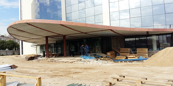
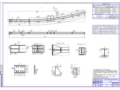
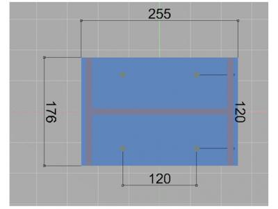
Structure visor total of about 200 m2 composed of a metal frame on the basis of the I-section girders (26SH1 GOST 26020-83), which are interconnected by means of girders bent channel (50h180h4 GOST8278-83). The supporting column in the center of the visor made of I-section beams (26SH1 GOST 26020-83). Additional columns are installed in the input group are made of square pipes (GOST8639-82 100h9). Material bearing steel - steel 09G2S.
Sheathing visor using the C35 occurs on trapezoidal sheet purlins so that the received packet does not go beyond the I-beams, which greatly facilitates the subsequent finishing work. Top additional sheathing is two sheets CFB thickness of 8 mm, followed by laying soft waterproofing and roofing.
Input work of the project team set of documentation was released, including the settlement and explanatory note and drawings album marks KM / KMD.
Cash-explanatory note includes:
- a description of the calculation scheme (model, communication materials);
- loading design (own weight, snow load);
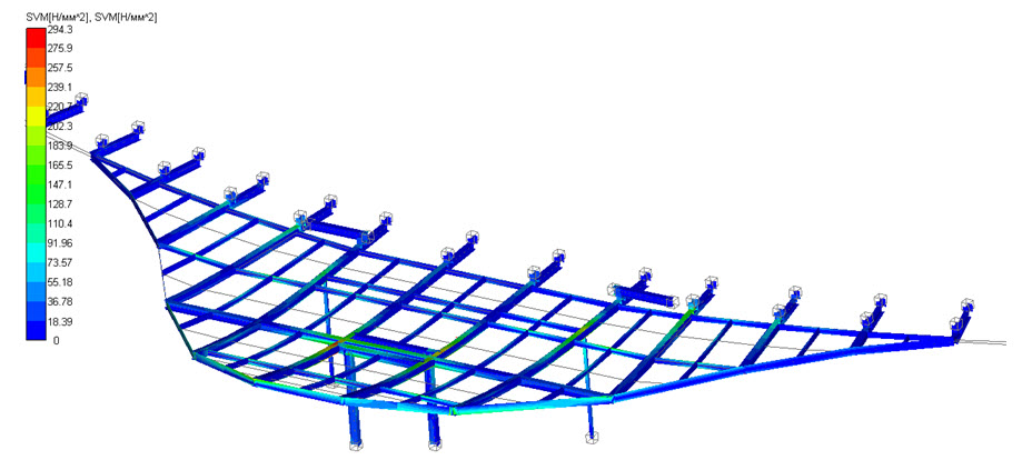
- calculation and analysis of the results (stress analysis, displacements);
- checking nesushey sposoobnosti according SP 16.13330.2011 Steel structures;
- calculation of bolted joints;
- calculation and selection of the anchor bolts.
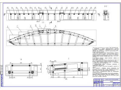
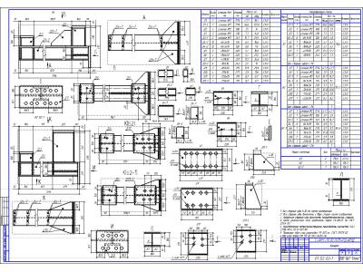
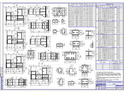
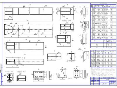
Album of drawings of marks of KM / KMD includes:
- a list-departure stamps;
- selection of metal products;
- a sample of steel;
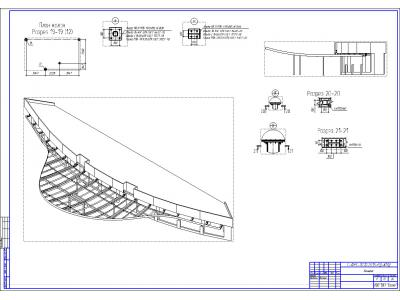
- anchoring plans;
- wiring diagrams and components;
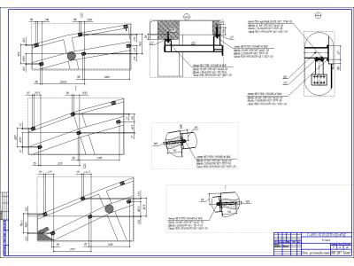
- detailed drawings of all-departure stamps.
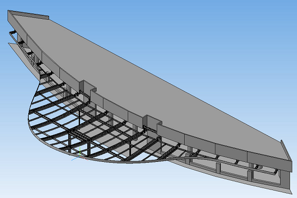
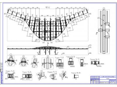
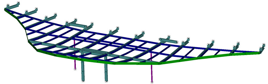
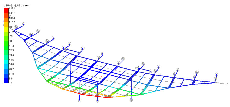
Calculated design visor circuit is implemented APM Structure3D system. Metalwork visor is attached to the foundation in the columns and the walls of the building. A total of 42 models of reference points. In addition to its own weight load design complemented by uploading "Snow evenly" or "Snow Bag".
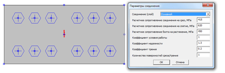
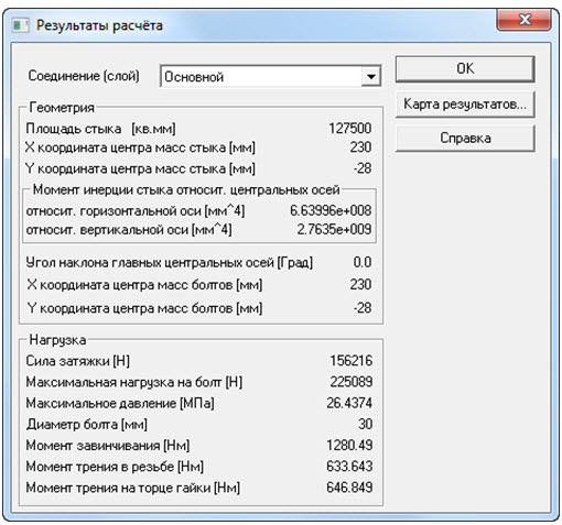
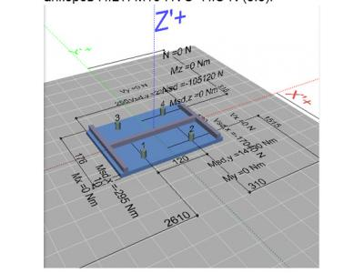
Calculation of the compounds was carried out in the APM Joint system. All flange connections are made on the visor design high-strength bolts. According to the SP 16.13330.2011: Class 8.8 bolts. Calculation of bolted connections are made using APM Joint module.
Selection of anchor bolts in specialized program PROFIS Anchor 1.9.0, which is designed for the selection of anchors Hilti. Calculation results of the modified anchor compound showed that it is recommended to use chemical anchors anchor HILTI M16 HVU + HIS-N (8.8).
Analysis static analysis results shows that the predetermined design loads, equivalent stresses arising in the sun visor structure elements using these sections do not exceed the yield strength of the materials used, i.e. necessary strength is provided. The most unfavorable case is a loading combination "Snow bag weight +" safety factor of 1.25 is the yield stress.
Check the bearing capacity of the visor columns showed that all operating conditions coefficients have values less than one, it is permissible and acceptable work suggests elements. Thus, we can conclude that the load capacity structures of data elements is provided.
The calculation of bolted joints showed that all compounds should produce high-strength bolts class 8.8 with controlled tightening torque.
Summarizing the results, we can conclude that the canopy structure is able to bear the load applied to it, corresponding to the construction site.


