Strength calculations of pipelines and equipment NPP

In keeping
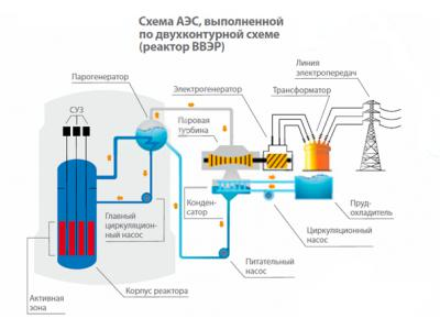
After more than half a century since its birth, nuclear power occupies a significant share of the world production of electricity. The number of nuclear power plants is constantly growing in the world. Already at the plant accounts for a significant portion of the energy produced in the world. And the trend shows that this proportion will increase in the future. There is no doubt that the production of energy with the use of peaceful nuclear energy is currently the most appropriate in terms of efficiency and environmental performance. At the same time in the event of nuclear accident the consequences can be very severe. Therefore, the main question, which is set at present in the countries on whose territories are constructed or operated nuclear power plants, as well as the IAEA international organization - is the safety of nuclear power plants. In this issue a very important role is played by the strength and reliability of nuclear power plant components.
Technically atomic power plant is a complex system consisting of a large number of components and equipment associated with each other conduits. The total length of the pipelines on the powerful nuclear power plant - a few kilometers
Ensuring the durability of equipment and pipelines of nuclear power units is one of the major challenges, not only in design, but also during operation. Construction equipment and pipelines should ensure availability, reliability and safety of operation during the service period specified in the technical specifications or data sheets for the equipment. These requirements determine the direct connection between regulations and strength elements, efficiency, reliability and safety.
calculation procedure
Evaluation of the strength of nuclear power stations in the Russian Federation is carried out in accordance with the "Standards based on the strength of the equipment and pipelines of nuclear power" plants "(PNAE G-7-002-86).
Justification strength to extend the life of the equipment can be performed based on one of two positions:
- on the actual operating conditions, the actual geometry of the actual elements and the mechanical properties of the materials used in the manufacture;
- how to calculate strength in technical design products for a full term of operation, taking into account its extension.
The second position may be used, if in the course of the last operation is not recorded deviations from operating conditions, defects or reducing the size of excess of the project.
Norms ... "regulated conduct strength calculation in two stages:
- first stage - calculation of the choice of the main dimensions;
- the second stage - checking calculation.
As a result of the first stage of the calculation are determined by the basic geometrical sizes of elements of nuclear power plants. Calculation of the choice of basic size is held at design pressure and temperature.
Calculated at the choice of the main dimensions calibration calculation is carried out, which is held on the nominal dimensions of the elements. Checking calculation includes calculation of static strength, fatigue strength, stability, calculation of seismic action, calculation of resistance to brittle fracture, the calculation of the progressive forming, and others. The calculations are determined value existing design stresses and deformations which are compared with permissible values ( settlement groups stress categories) listed in normahPNAE Mr. 7-002-86.Pri original calibration calculation takes into account all the existing loads and covers all modes of Expl are being published (normal operating conditions, hydraulic or pneumatic tests, violations of normal operating conditions, seismic effects).
In accordance with the IAEA analysis of seismic resistance of equipment and pipelines of nuclear power plants in operation guidelines, carried out using the so-called method of boundary seismic resistance (MAP) ( "Evaluation of Seismic Safety for Existing Nuclear Installation" Safety Standards Series). The method consists in the determination of boundary seismic resistance (HCLPF parameter). To calculate the boundary HCLPF earthquake resistance is used ratio seismic stock FS.
The existing standards are recommended methods for calculating the standard elements and assemblies of pipelines and nuclear power plants based on the methods of elasticity and structural mechanics. Since the technique is to use a "manual" calculation of pipelines and equipment, its use is not without significant design simplifications which lead to decomposition calculated object into simple elements. Further, these elements are calculated separately, and the influence of neighboring elements are taken into account by introducing appropriate boundary conditions. This approach is not accurate enough in the case of complex structures, such as the simplification of making large error in the results.Such phenomena as stress concentration in the areas of abrupt change in geometry accounted introducing stress concentration factor. Determination of its value is often very challenging. A calculation of criteria such as resistance, earthquake resistance is even more complicated.
Thus, all of these problems suggest that now - time information technology, "manual" calculation of strength in the field of nuclear energy is unacceptable from the point of view of the required accuracy of calculation and labor. This suggests the use of numerical methods for modeling and analysis of complex structures
Examples of nuclear power plants
Calculations using APM WinMachine
Computer-aided design of mechanical constructions and equipment in engineering and construction APM WinMachine can meet the challenges of strength, thermal analysis, spectral analysis, ie those tasks necessary for the calculation of residual life or prolong the life of pipelines and nuclear power plants.
Estimated core APM WinMachine system - module APM Structure3D - has №330 attestation certificate from April 18, 2013
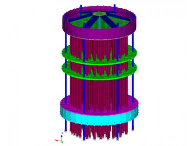
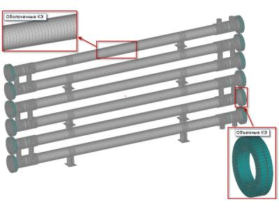
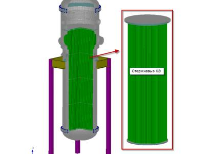
In constructing models of equipment and pipelines of nuclear power plants use the following set of finite elements from the library to APM WinMachine (Figure 1.)
- shell elements (4 junction 3 and the nodal plate) shells for modeling pipes, condensers, elliptic or flat bottoms, etc .;
- volume elements (4 and node 10 node tetrahedra, 8-node hexahedron) to simulate thick shells, tube plates, flanges, supports and t. d .;
- rod members (beams) to simulate the heat exchanger tubes, bolts and studs flange connections, etc .;
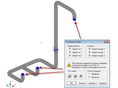
In the case of piping modeling, the following types of support:
• rigid support, eliminating all displacements and rotations (Fig 2a.);
• one-sided support for the simulation of sliding bearings;
• guide bearings;
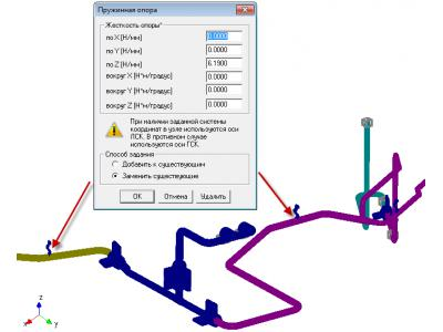
• elastic binding to simulate spring supports / hangers (Fig. 2b).
Calculation of pipelines and nuclear power plants was carried out using the module for calculating the stress-strain state, stability, natural and forced vibrations of parts and structures using finite element method - APM Structure3D, included in the APM WinMachine system. This module allows you to create a computational model, close enough to describe the geometry of the computed nodes
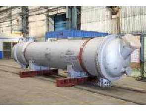
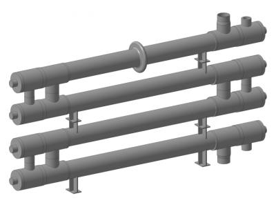
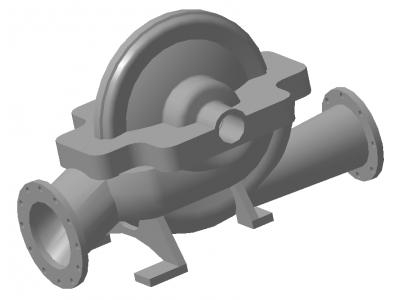
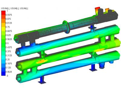
Static strength calculation is performed for all possible modes of operation of the equipment (Figure 3). The operating mode is determined by the mechanical loads and temperature conditionS.
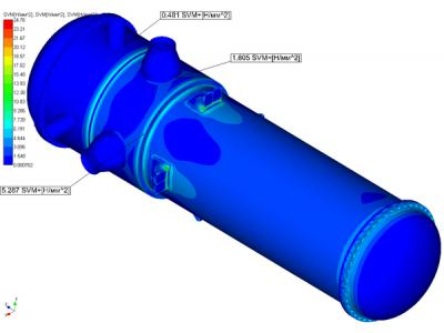
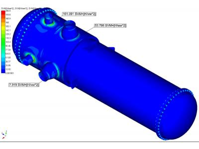
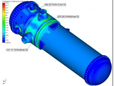
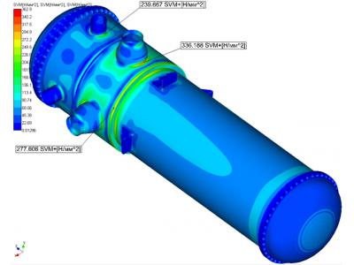
Fig. 3 Distribution reduced stress in the heat exchanger cooling the cooling pond
When per ring strength selected calculation points in zones of stress concentration and determined the accumulated fatigue damage at these points
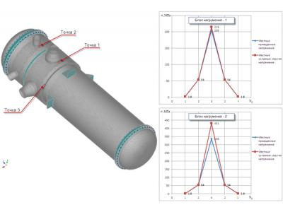
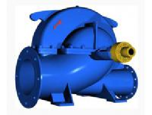
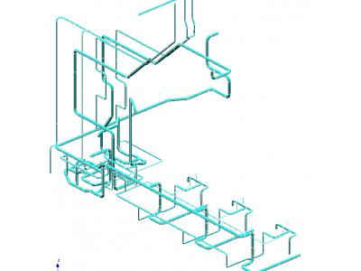
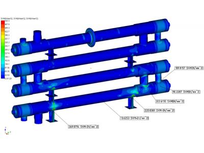
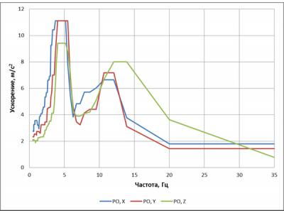
Calculation of seismic effects operate linearly spectral method (in response spectra) or the method of dynamic analysis (for accelerograms). Below are the results of calculation of seismic resistance purge aftercooler (Fig. 4). Seismic loads were determined using spectra of floor level MDE response to mark 23.5 m (Fig. 5).
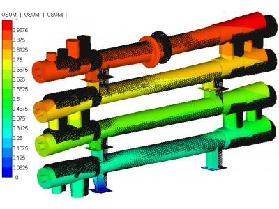
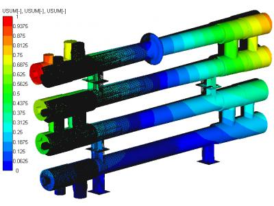
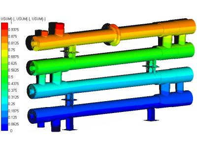
Proper form aftercooler purge oscillations
conclusion
Thus, the work described indicates that APM WinMachine system can be successfully used to evaluate the strength of the atomic power plant equipment.
Using APM WinMachine for such calculations enables to fulfill all requirements of "Standards based on the strength of the equipment and pipelines of nuclear power plants" (PNAE G-7-002-86), making the work easier and saves time.


