6. M. Cyrus and J. Beck. Generalized Two- and Three-Dimensional Clipping. Computers & Graphics, Vol. 3, pp. 23-28, 1978.
UM 3D Contact
3D Contact simulation module - Introduction - Applications - Theory in short.
Introduction
UM 3D Contact module allows simulating of contact interaction of bodies by contact manifolds (graphical objects). The realized contact algorithm is based on the simulation of interaction of arbitrary convex polyhedrons. The set of supplied primitives includes the following types: box, cylinder, cone, ellipsoid, and polyhedron.
To allow the simulation of contact interactions, user should set contact manifolds to bodies. Only bodies with contact manifolds will interact between each others. The parameters of contact interaction of each pair of bodies can be defined and turned on/off additionally.
The graphical object of a body may be not similar to the graphical object of a contact manifold. Rough description of a contact manifold is used to reduce computational efforts of the simulation of contact interactions, for example in real-time simulation tasks. Moreover the model of 3D contact supports the parameterization of primitives. It allows considering various configurations of interacted bodies just by changing the corresponding parameters.
The contact force model includes the viscous-elastic normal component and the dry friction force in both sliding and sticking modes.
Application
The module of 3D contact substantially extends the abilities of contact interaction simulation in Universal Mechanism and the field of solving tasks. Today several commercial projects already use UM 3D Contact module. We hope that the new realized abilities allow our users to create more realistic and adequate models.
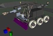
Sample 1: robotics
Robotics is one of practically important applications of the module. In real time simulation of wheeled and tracked robot dynamics, all the kinds of contact interactions are taken into account. The set of interactive bodies includes robot parts, scene objects and obstacles as well as ground surface with its complex shape. Manipulation of scene objects by manipulator clamp of robot, collisions of structural elements of robot and obstacles on the scene, rolling of robot wheels on the complex ground surface are simulated in this model.
Some results of the KRT-2001, 2 robot simulation are available by the following links:
1 The model of KRT-200 robot is developed by specialists of Engineering-Technical and Educational Center of Robotics (ETECR) state corporation "Rosatom". Authors express their gratitude to ETECR and personally to Valery Nikitin for provided materials.
2 The model with control panel is included in samples of UM, see ..samples/robots/krt_200.
Sample 2: Stability of an antique column
In the second sample stability of the antique column during earthquake is considered3, 4. The pedestal of the column stands on a surface which moves in 3 directions according to the measured data during real earthquake. The model includes three bodies: the pedestal, the column and the capital. Contact manifolds of the bodies correspond to their graphical objects.
3 The model is developed in Department of Earthquake Geology, Geological Institute, University of Cologne, Germany. Authors express their gratitude to professor Klaus-G. Hinzen for provided materials.
4 The model is included in samples of UM, see ..samples/misc/earthquake.
Sample 3: frictional wedge of three-pieces bogie
Another sample of using 3D contact is simulation of a friction wedge system of a three-piece bogie of a freight car5. All contact interactions between elements of the system (a frictional wedge, a bolster and a side frame) are realized according to methodology of 3D contact module. Thus a contact manifold based on corresponding graphical object was created for each body. These graphical objects were imported from a CAD-model.
Note that the considered model includes several elements of three-piece bogie of freight car. This model is created only for testing of such damping friction systems and for demonstration of 3D contact module abilities. Movement of the bolster is specified by the time-function that expressed via parameters for its amplitude and frequency.
Some results of the simulation are available by the following links:
5 This model is included in samples of UM, see ..samples/rail vehicles/wedgetest3dcontact.
Theory in Short
The approach treats nondeformable 3D objects with small overlaps at the contact. The presented approach consists of two parts: collision detection for arbitrary polyhedrons and then a contact force calculation. Collision detection deals with generalized three-dimensional clipping algorithm by Cyrus and Beck6. Contact force calculation is based on a point-plane model and computed as the sum of normal viscous-elastic and tangential dry friction forces.
To accelerate computational processes the collision detection is typically divided into so-called far and near collision detection problems. The far collision detection is usually a fast algorithm that should select polyhedrons for the following, usually more time-consuming, near collision detection. On the first stage of the far collision detection circumscribed spheres around polyhedrons are created and its intersection is checked. The polyhedrons that passed through the far collision detection are treated by a near collision detection algorithm.
The well-known in computer graphics the generalized three-dimensional clipping algorithm by Cyrus and Beck is used as the near collision detection algorithm. The algorithm deals with two convex polyhedrons and gives as a result clipped edges of one polyhedron that lie within another one and vice-versa.
After all collisions between the neighboring polyhedron pairs have been detected, the contact forces have to be determined. Having a set of clipped edges that belong to each polyhedron, the algorithm of calculation of contact forces arranges contact points on each edge. Then for each contact point the nearest face on another polyhedron from the pair is determined. As soon as pairs of points and planes (faces) are obtained, the contact force R can be calculated as the superposition of normal viscous-elastic force N depending on penetration Δ and its derivative, and tangential dry friction force Ff


